Volkswagen Golf 5 th generation was produced in 2003, 2004, 2005, 2006, 2007, 2008 and 2009 mainly in the hatchback, with both petrol and diesel engines. In our material you will find a designation of the Volkswagen Golf 5 fuse boxes and relays with diagrams and photographs. Let’s show the location of all electronic control units. Separately, we note the fuse responsible for the cigarette lighter. This material will also be useful to the owner of Volkswagen Jetta 5 cars, since these models have a similar electrical circuit.

Generation not right? Study the description for 4 or 6 respectively.
Contents
Layout
Diagram

Designation
| 1 | Air conditioner electronic control unit |
| 2 | Air conditioner / heater fan motor control unit |
| 3 | Side impact sensor, driver’s side |
| 4 | Side impact sensor, rear left |
| 5 | Side impact sensor, passenger side |
| 6 | Side impact sensor, rear right |
| 7 | Vehicle tilt sensor (anti-theft system) |
| 8 | Accumulator battery |
| 9 | Diagnostic connector (DLC) |
| 10 | Data bus connector |
| 11 | Driver’s door electrical control unit – in the door |
| 12 | Rear left door electrical control unit |
| 13 | Control unit for electrical equipment of the passenger door – in the door |
| 14 | Rear right door electrical control unit |
| 15 | Cooling fan motor control unit – on the cooling fan motor |
| 16 | Fuse / relay box, engine compartment 1 |
| 17 | Fuse / relay box, engine compartment 2 |
| 18 | Fuse / relay box, engine compartment 3 – under engine fuse / relay box 1 |
| 19 | Fuse / relay box, instrument cluster 1 |
| 20 | Fuse / relay box, instrument panel 2 |
| 21 | Fuse / relay box, instrument cluster 3 |
| 22 | Headlight range control unit (models with xenon headlights |
| 23 | Heater blower motor resistor |
| 24 | Beep 1 |
| 25 | Beep 2 |
| 28 | Instrument cluster control unit |
| 29 | Multifunction control unit 1 – in the dashboard fuse / relay box 3 – functions: Cigarette lighter, cruise control, fog lights, hazard warning lights, headlights, rear window defogger, horn, interior lights, rear window wiper / washer, reversing lights , front dimensions, brake lights, windshield washer, windshield wiper |
| 30 | Multifunction control unit 2 – functions: Anti-theft system, tailgate / tailgate lock, tailgate / tailgate opener, central locking, power door mirrors, power windows, drive for opening the fuel filler flap, sunroof |
| 31 | NOx sensor control unit – under the body |
| 32 | Parking system control unit – luggage compartment right |
| 33 | Power steering control unit – above the steering rack |
| 34 | SRS electronic control unit |
| 35 | Steering column electronics control unit |
| 36 | Telephone control unit – under the seat, if fitted |
| 37 | Trailer control unit – left luggage compartment |
| 38 | Electronic gearbox control unit – behind the wheel arch |
| 39 | Windshield wiper control unit – on the resonator of the intake system |
Engine compartment
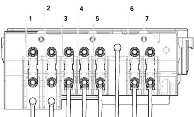
Fuse and relay box is located next to the battery and is covered by a protective cover. Consists of two boxes. 1 – Department of high power fuses in the form of fusible links. 2 – section of fuses and relays.

Fuse and relay box
Type 1
Photo for example

Diagram
Appointment
| 1 | Engine control relay |
| 2 | Outlet air pump relay |
| F1 | (30A) Windscreen wiper |
| F2 | (5A) Steering column electronics control module / (30A) DSG gearbox mechatronic unit |
| F3 | (5A) Onboard supply control unit |
| F4 | (30A) ABS control module |
| F5 | (15A) Gearbox control module |
| F6 | (5A) Instrument panel |
| F7 | (40A) Power relay |
| F8 | (15A) Audio system / Head unit |
| F9 | (5A) Telephone control unit |
| F10 | (5A / 10A) Electronic engine control unit |
| F11 | (20A) Auxiliary heater control unit |
| F12 | (5A) CAN data bus, gateway control unit |
| F13 | (15A / 30A) Electronic engine control unit |
| F14 | (20A) Engine management system, ignition coil |
| F15 | (5A / 10A) Engine management system, Lambda probe |
| F16 | (30A) ABS control module, RH headlight |
| F17 | (15A) Horn |
| F18 | (30A) Audio system |
| F19 | (30A) Windshield wiper / washer |
| F20 | (10A) Coolant pump |
| F21 | (10A / 15A) Engine management system, Lambda probe, Drive blower magnetic clutch |
| F22 | (5A) Clutch pedal position switch |
| F23 | (5A / 10A / 15A) Engine management system, Fuel pressure regulator, Secondary air pump relay |
| F24 | (10A) Engine management system, EGR valve, Solenoid valve |
| F25 | (40A) ABS control unit |
| F26 | (30A) LH headlamp |
| F27 | (50A) Glow plug control module |
| F28 | (40A) Main ignition circuits |
| F29 | (50A) Thermal fuse 1 for seat adjustment |
| F30 | (40A) Starting system (50A) Relay for unloading contact X |
Type 2
The photo

Diagram
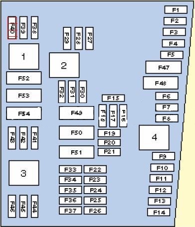
Designation
| 1 | Relay 2 main ignition circuits |
| 2 | Starter relay |
| 3 | Fuel pump relay – 1.4 (BCA) / 1.6 (BGU) |
| 4 | Relay 1 of the main ignition circuits |
| F1 | (30А) ABS |
| F2 | (30А) ABS |
| F3 | (20A) Multifunction control module 2 |
| F4 | (5A) Multifunction control module 1 |
| F5 | (20A) Horn |
| F6 | (5A / 20A) Engine management |
| F7 | (5A) Brake light switch (brake pedal position sensor), clutch pedal position sensor |
| F8 | (10A) Cooling fan motor control module, engine management |
| F9 | (10A) Engine management |
| F10 | (10A) Engine management |
| F11 | (25A) Engine management – petrol |
| F12 | (15A) Engine management |
| F13 | (20A) Automatic transmission |
| F14 | – |
| F15 | (40A) Starter |
| F16 | (15A) Steering column electronics control module |
| F17 | (10A) Instrument panel |
| F18 | – |
| F19 | (15A) Audio system, navigation system |
| F20 | (10A) Telephone |
| F21 | – |
| F22 | – |
| F23 | (10A) Cruise control system |
| F24 | (10A) Data bus connector |
| F25 | – |
| F26 | (5A) Engine management – Diesel |
| F27 | (10A) Crankcase ventilation heater |
| F28 | (20A) Automatic transmission |
| F29 | (20A) Engine management |
| F30 | (20A) Heater / air conditioner |
| F31 | (25A) Windshield wiper |
| F32 | (10A) Engine management |
| F33 | (15A) Fuel booster pump |
| F34 | – |
| F35 | – |
| F36 | – |
| F37 | – |
| F38 | (10A) Headlight range control |
| F39 | (5A) Engine oil temperature sensor, instrument cluster |
| F40 | (20A) Dashboard fuse / relay box 1 (F1-F11 / F29-F31) |
| F41 | – |
| F42 | (5A) Engine management – Petrol |
| F43 | – |
| F44 | – |
| F45 | – |
| F46 | – |
| F47 | (40A) Multifunction control module 1 |
| F48 | (40A) Multifunction control module 1 |
| F49 | (50A) Multifunction control module 1 |
| F50 | (40A) Audio system |
| F51 | (50A) Glow plug control module |
| F52 | (50A) Multifunction control module 1 |
| F53 | (50A) Dashboard fuse / relay box 1 (P32-B37), Dashboard fuse / relay box 2 (F4) |
| F54 | – |
Fuse box
Type 1
Functions
- 150A / 200A – Generator
- 80A – Power steering control unit
- 50A – Radiator fan and its control unit
- 40A – Low power heating relay or Additional equipment
- 100A – Fuses in the cabin
- 80A – Fuses in the cabin, 100A – optional
- 30/40 / 50А – Trailer connection and additional equipment
Type 2

Designation
- 150A / 200A – Generator
- 80A – Steering booster unit
- 50A – Radiator fan and its control unit
- 40A – Fuses in the cabin
- 100A – Fuses in the cabin, 80A – additional equipment
- 80A – Fuses in the cabin, 100A – optional
- 50A – Reserve
In some models, additional relays may be located outside the unit: the glow plug control relay and the air supply pump relay.
Passenger compartment
Fuse box
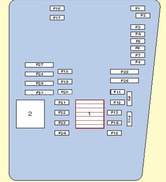
It is located at the end of the dashboard on the driver’s side behind the protective cover.

Diagram

Assignment
| F1 | (10A) Diagnostic connector DLC, Engine control unit, Relay for auxiliary heater operation |
| F2 | (5A) ABS, ESP |
| F3 | (10A) Power steering, (5A) airbag control module |
| F4 | (5A) Heated seats, heater / air conditioner, air conditioning control unit, oil level and temperature sensor, reversing light |
| F5 | (5A) Brake light switch (brake pedal position sensor), clutch pedal position sensor, control unit for adaptive lighting and headlight range control, on the right headlight |
| F6 | (5A) Data bus connector, engine management, control unit in instrument cluster, control unit for adaptive lighting and headlight range control, on the left headlight |
| F7 | (5A) Headlamp leveling control module, interior mirror |
| F8 | (5A) Interior rearview mirror, (10A) – Trailer control unit |
| F9 | (5A) 4WD electronic control unit, navigation system |
| F10 | (5A) Telephone, seat occupied detection unit |
| F11 | (5A) Trailer control module |
| F12 | (10A) Door control module (driver), door control module (passenger), central locking |
| F13 | (10A) Diagnostic socket, light switch, rain and light sensor |
| F14 | (5A) Brake light switch (brake pedal position sensor), automatic gearbox control unit, ABS control unit |
| F15 | (7.5A) Multifunction control module (interior lighting) |
| F16 | (10A) Heater / air conditioner, antenna selection control unit |
| F17 | (5A) Audio system, rain sensor (windshield wiper), anti-theft alarm horn |
| F18 | (5A) Parking control module, selector lever position sensor |
| F19 | (5A) Emergency data logger |
| F20 | (5A) Anti-lock braking system |
| F21 | (5A) Control unit for maximum engine speed limitation, front left footwell (special vehicles) |
| F22 | (40A) Supply fan |
| F23 | (30A) Power windows, door control module |
| F24 | (25A) Cigarette lighter fuse, front and rear, convenience system central control unit |
| F25 | (25A) Multifunction control module (rear window heater, air conditioner control unit, heater and operating mode selection switch) |
| F26 | (20A) Charging connector (socket) (25A) Rear door control unit |
| F27 | (15A) Engine management (fuel pump) |
| F28 | (25A) Inverter with socket for special vehicles |
| F29 | (10A) Engine management |
| F30 | (5A) Airbag (10A) Injectors (20A) automatic gearbox control unit |
| F31 | (5A) Reversing lights (20A) Brake vacuum pump |
| F32 | (15A) Power windows |
| F33 | (25A) Luke |
| F34 | (15A) Power seats |
| F35 | (5A) Anti-theft system |
| F36 | (20A) Headlamp washers |
| F37 | (30A) Heated seats |
| F38 | (20A) Horn relay, anti-theft alarm, convenience system central control unit |
| F39 | – |
| F40 | (40A) Heater / air conditioner |
| F41 | (15 / 20A) Rear window cleaner / washer |
| F42 | (15 / 20A) Windshield washer, Cigarette lighter |
| F43 | (15A) Trailer control module |
| F44 | (20A) Trailer control module |
| F45 | (15A) Trailer control module |
| F46 | (5A) Air conditioning / heating system, heater and windshield washer nozzles |
| F47 | (5A) Heater / air conditioner |
| F48 | (7.5A) Power Seat, Steering Column Adjustment Drive, Mag-Lite Flashlight and Walkie Talkie Charger |
| F49 | (7.5) Light switch |
Depending on the configuration and year of manufacture, fuses 24 or 42 are responsible for the cigarette lighter.
Relay box
The relay box is located under the dashboard on the driver’s side and consists of 2: main and additional.

Main
Diagram

Designation
| 1 | – |
| 2 | Heated mirror relay |
| 3 | – |
| 4 | Relay for multifunction control unit |
| 5 | Heated rear window relay |
| 6 | Horn relay |
| 7 | Windshield washer pump relay 1 |
| 8 | Windshield washer pump relay 2 |
| 9 | Relay for auxiliary ignition circuits |
Additional
Diagram

Appointment
| 1 | Headlight washer pump relay |
| 2 | Booster Fuel Pump Relay – Diesel |
| 3 | Starter relay |
| 4 | Headlight washer pump relay |
| 5a | Start relay (fuel system) |
| 5b | Relay for auxiliary heater |
| A | 30A Thermo fuse 1 for adjusting the position of the driver’s seat |
| B | 30A Thermo Fuse 2 Seat Adjustment Driver |
We have posted a video on our YouTube channel. Watch and subscribe.
Still have questions? Ask them in the comment and we will try to help.
Hi
Can anyone help me with the diagram and relay for Vw Jetta 5, 2009 model
Hi help me with my fuel pump of golf 5 model 2005
Can someone help me with diagram of relay and fuse panels for 2008 Vw Jetta im having trouble figuring out why my blower for my heat isn’t working already replaced blower motor
Did you find any solutions ?
Need help my VW Golf MK5 08 1.9 keeps cutting out, someone said it could be relays etc, after breaking down the first time. I bought a new fuel pump, and all new sensors, map sensor,maf sensor,crank position sensor, changed filters air,fuel etc and have done an oil change, cleaned egr, injector clean, injector wiring loom but still doing the same thing….. can someone help me please
My car have code p0685 ECM/PCM control power relay circuit open, no Epc and engine light the car just crank but don’t start which relay should I replace and the location
It’s a golf 5 gti BWA engine.
Its the Crankshaft Position Sensor located behind the oil filter.
Having a problem with my son’s 09 Golf GTI. The passenger headlight isn’t working, then the passenger taillight and brake light went out. Replaced the bulbs, they all worked for 2 days then went out. Now we have no lights on the passenger side. No headlight or taillights. I’m stuck. Maybe a wiring problem? Maybe a relay going bad? I can’t figure it out. Any help would be appreciated.
Thanks.
Hello my friend, can you catalog the fuse box of the Golf R32 2008 please?
My golf 5 gear is not selecting whenever day work on the car what is the condition ND i used computer is showing ecu power relay is down were is ECU power relay located
Thanks for this extremely helpfull browser.
Thank you for the helpful browser.
Hello. Can’t get ac unit to kick in. New pump and sensor. Is there a ac clutch sensor relay or fuse for golf mk5 fsi 1.6 thankyou.
I’m looking for the fuse/relay for the driver’s side power seat on a 2010 Jetta SE. Ever since water got in and accumulated in the Driver’s side foot well, the power seat doesn’t work anymore. I’ve already cleaned out the connectors, and the passenger’s side power seat works, just can’t find any info about the driver’s side fuse/relay location.
Anthony Hayes
check wiring loom at the gearbox(around starter) they go bad and touch eachother
Could you please help and email a wiring diagram as well as fuse and relays info for a 2009 Jetta (A5) MK5 , the fuse box in the engine compartment in my car are different to those Type 1 and 2 shown, mine only has 1 relay numbered as (100) and there are only 17 fuses inside the car, I am currently having a crank no start and it is very expensive to call out a technician.
Where is the indicator flasher unit of the VW Jetta 5 TDI. My indicators are not working but emergency lights Hazards are working.
My horn (hooter) is not working as well.
What do I do?
My radiator fan is not working. Where is it’s relay situated? 2008 Golf 5 TDI
Hi
Im having problem with my gti golf5 no engine ligth , no EPC ligth everythigs ok ( like fuses relays ext.) Dont know where to start please hel neeted here.
hey what’s the fuel pump relay or fuse for a 2007 volkswagen rabbit 2.5
The image used for the Engine Fuse Box Type 2 has incorrect fuses placed (like F10, F31) which you can clearly see yourself by matching up the descriptions underneath. Whoever worked on the used car I purchased used this incorrect image, which has caused all sorts of issues including tail lights and break lights so whoever mentioned that – double check the fuse and amp descriptions underneath and not the image itself.