The 6th generation Volkswagen Golf compact car was produced with hatchback, station wagon and convertible bodies in 2008, 2009, 2010, 2011, 2012 and 2013. In our material, a designation of the Volkswagen Golf 6 fuse boxes and relays will be presented with diagrams and photo examples. Separately, we highlight the fuse responsible for the cigarette lighter.

If the generation of the model is not suitable, then read the description for 5 and 7, respectively.
Contents
Engine compartment
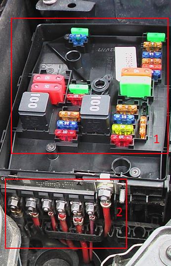
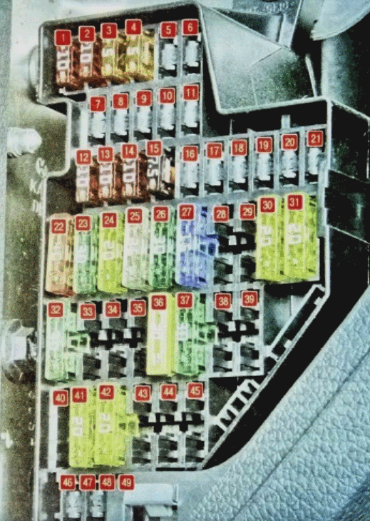
Located on the left side of the underbelly space and covered with a protective cover. Consists of two parts: 1 – relay and fuse box and 2 – high power fuse box.
Fuse and relay box
Diagram
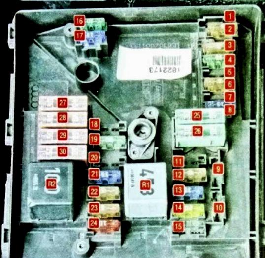
Description
| R1 | ECU Relay / Fan Relay |
| R2 | Air blower pump relay / Automatic gearbox control relay |
| 1 | (30A) Wiper motor |
| 2 | (30A) Gearbox mechatronic unit |
| 3 | (20A) Onboard supply control unit |
| 4 | (20A) ABS control module |
| 5 | (15A) Transmission control module (ECM) |
| 6 | (5A) Instrument panel, Steering column control module |
| 7 | (40A) Power supply relay cl. fifteen |
| 8 | (15A) Audio system, Head unit (25A) Voltage stabilizer |
| 9 | (5A) Telephone control unit |
| 10 | (5A / 10A) Electronic engine control unit, Motronic power relay |
| 11 | (20A) Auxiliary heater control unit, Auxiliary heater relay |
| 12 | (5A) CAN data bus, gateway control unit |
| 13 | (15A / 30A) Electronic engine control unit |
| 14 | (20A) Fuel booster pump, Ignition |
| 15 | (5A / 10A) Glow plug relay, Fuel pump relay, Lambda probe |
| 16 | (30A) Lamps and headlights – right side |
| 17 | (15A) Horn |
| 18 | (30A) Audio system, Amplifier |
| 19 | (30A) Windshield wiper / washer |
| 20 | (10A) Coolant circulation pump (20A) Fuel pressure regulating valve |
| 21 | (10A / 15A) Lambda probe heater, Central locking motor in front passenger door (20A) Brake vacuum pump |
| 22 | (5A) Clutch pedal position switch |
| 23 | (5A / 10A / 15A) Engine management system |
| 24 | (10A) Engine management system (pump relay, injectors, etc.) |
| 25 | (40A) ABS control unit |
| 26 | (30A) Lights and headlights – left side, onboard supply control unit |
| 27 | (40 / 50A) Glow plug control unit, Secondary air pump motor |
| 28 | (30A) Terminal 15 power supply relay 2 |
| 29 | (50A) Thermal fuse 1 for driver’s seat adjustment |
| 30 | (50A) Relay for unloading contact X |
Fuse box
Type 1
Diagram
Designation
- 150A / 200A – Generator
- 80A – Power steering control unit
- 50A – Radiator fan and its control unit
- 80A – Heating relay or Additional equipment
- 80A – Terminal 30, passenger compartment fuse box
- 40A – Low power heating relay
- 30/40 / 50А – Reserve
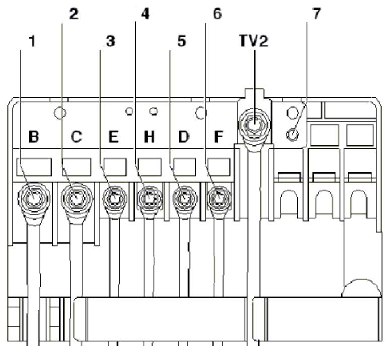
Type 2
Diagram

Functions
- 150A / 200A – Generator
- 80A – Steering booster unit
- 50A – Radiator fan and its control unit
- 80A – Reserve
- 80A – Terminal 30, passenger compartment fuse box
- Reserve
- Reserve
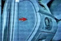
Passenger compartment
Fuse box
Located at the end of the dashboard on the driver’s side, behind the protective cover.
Diagram
Appointment
| F1 | (10A) DLC connector, Engine control unit, Relay for auxiliary heater operation, Dimmer for switches and instrument cluster, Headlight range control, Adaptive cruise control unit, Brake light switch |
| F2 | (5A) ABS, ESP, Instrument cluster control unit, Engine control unit, Starter relay, Power steering control unit, Trailer detection control unit |
| F3 | (5A) Airbag control module |
| F4 | (5A) Oil level and temperature sensor, High pressure sensor, Engine oil level and temperature sensor, ASR and ESP deactivation button, Tire pressure indicator button, Airbag control unit |
| F5 | (10A) Left headlight control module |
| F6 | (10A) Right headlight control module |
| F7 | Reserve |
| F8 | Reserve |
| F9 | Reserve |
| F10 | Reserve |
| F11 | Reserve |
| F12 | (10A) Door control module (driver), door control module (passenger), central locking |
| F13 | (10A) Diagnostic socket, light switch, rain and light sensor, fog lamp switch |
| F14 | (10A) Brake light switch (brake pedal position sensor), automatic gearbox control unit, Climatronic control unit |
| F15 | (20A) Button for unlocking, tailgate / tailgate handle, Onboard supply control unit, Central locking system |
| F16 | (10A) Rear view camera |
| F17 | (5 / 10A) Audio system, tilt sensor, alarm siren, signal relay |
| F18 | Reserve |
| F19 | (5A) Crash data logger, Engine speed limiter control unit |
| F20 | (20A) Entry and start authorization control module, voltage stabilizer |
| F21 | (10A) Electronic steering column lock control module |
| F22 | (40A) Supply fan |
| F23 | (30A) Power windows, door control module |
| F24 | (20A) Onboard supply control unit |
| F25 | (25A) Multifunction control module (rear window heater, air conditioner control unit, heater and operating mode selection switch) |
| F26 | (30A) Rear door control module and glass lifters |
| F27 | (15A) Engine management (fuel pump) |
| F28 | (15A) Voltage stabilizer, Head unit |
| F29 | Reserve |
| F30 | (20A) Automatic transmission control module |
| F31 | (20A) Brake vacuum pump |
| F32 | (30A) Inverter with socket, 12 V – 230 V |
| F33 | (25A) Luke |
| F34 | (15A) Power seats |
| F35 | (10A) Electronic damping control module |
| F36 | (20A) Headlamp washers |
| F37 | (30A) Heated seats |
| F38 | (20A) Horn relay, anti-theft alarm, convenience system central control unit |
| F39 | – |
| F40 | (40A) Heater / air conditioner |
| F41 | (15A) Glass cleaner motor |
| F42 | (20A) Cigarette lighter, 12V socket |
| F43 | (15A) Trailer control module |
| F44 | (20A) Trailer control module |
| F45 | (15A) Trailer control module |
| F46 | Reserve |
| F47 | (5A) Instrument cluster control module |
| F48 | (5A) Mobile phone control electronics control unit, Voltage stabilizer, Magnetic field sensor for compass |
| F49 | Reserve |
The fuse number 42, 20A, is responsible for the cigarette lighter.
Relay box
It is located under the dashboard itself, behind the trim.

Diagram

Upper relay box diagram
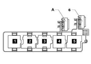
- Terminal + Ignition Switch Relay
- Horn relay
- Headlight washer relay
- Power circuit unloading relay
- Relay for electric window heating
- or A – 30A Thermal fuse 1 for adjusting the position of the driver’s seat
General description of the functions performed by the onboard power supply control unit : Control of relay circuits, Control of lighting devices, Power distribution between consumers, Control of windshield wipers (via LIN), Control of rain and light sensors, Turning on the sound signal, Control of heated windows, windscreen and rear, Saving personal settings , Management of the interior monitoring system, tilt sensors and burglar alarms, Convenient locking / unlocking, Remote control (built-in antenna), Central locking (control of locks, doors, hatches and covers), Tire pressure monitoring system (separate logic module with a diagnostic address) , Control of door control units, Lighting for traffic in the daytime, Static adaptive lighting system.
On our YouTube channel, we also posted a video. Watch and subscribe.
If you have something to supplement this material, write in the comments.
VW GOLF6 variant TSi station wagon 2010; how is the rear boot interior lamp return wired? 12V dc supplt comes but the does not light as tgere is no negative ground return likely through a relay or door switch. Tracing the wires they go to tge front not tge rear door?
Where is the relay that switches tge boit lamp?
Polo Vw tdi 1.9 2006 model
I have fuel primary circuit fault (P0230 fault code) so can any please help
With advice on how to go about fixing
I have a P0322 error.
It causes the engine to jerk then EPC light goes on & sudden loss in power.
What could be the cause & how do i fix it?
Check ur throttle body
I have a problem with the right handside lights, that is, headlights, brake lights, turn signals all not working on a 2010 TSI Golf VI. What could be the cause?
2010 tsi Golf
Turn key it starts, then dies. Scan tool gets 3/4 way through scanning and stops saying “connect error”
No power to radio and driving lights remain on while accessories on even though lights are off?
So confused 😕
Any advice or tips would be greatly appreciated.
2011 1.4 tsi mk6 golf.
P0031 code. Bought new sensor but it didnt fix the issue. Is there a fuse or relay that might have blown?
Hello
I have a problem with my front frog lights and the automatic headlight doesn’t work either
Can any help me?
Please
2010 golf 2.5 ac not turning on is this cause by fuse or relay and where would I found it
Any fuse is designed for the aircon only?
2012 golf no wipers no power windows no signals no high/low beam control
Code 79742 no bcm communication
Golf 6 Tsi no battery light no epc light no power to window