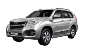
The first generation Haval H9 crossover was produced from 2014 to 2024. During this time, the model underwent several restylings. Currently, the second generation of the Haval H9 is in production. In this publication, you will find a description of the Haval H9’s fuses and relays, including fuse box diagrams, their locations, and photo examples. We will specifically highlight the fuse responsible for the cigarette lighter.
The purpose of some elements in the diagrams may differ from the one presented and depends on the year of manufacture, configuration and country of delivery. In case of difficulty, contact your nearest dealer.
Passenger compartment
It is located behind the glove compartment on the driver’s side. To access, pull firmly on the right side in the direction of the arrow.
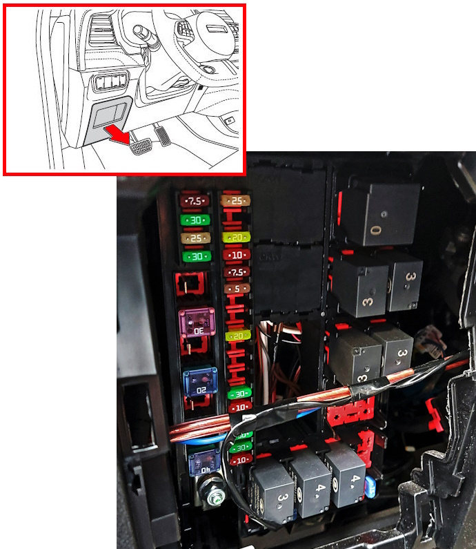
Type 1
Diagram
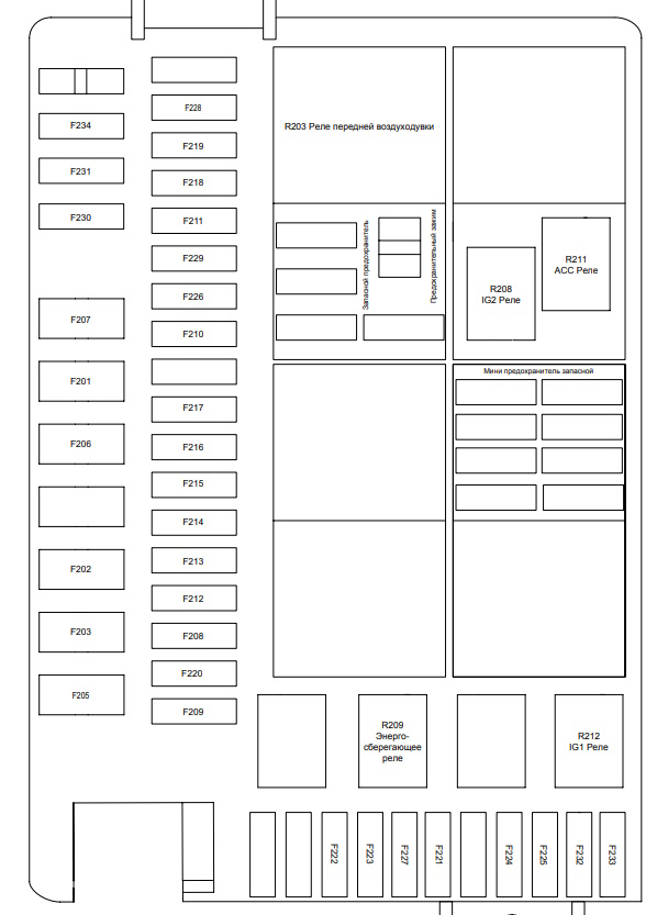
Assignment
| F201 | 40A (F-Blower) – Heater Blower |
| F202 | 30A (EPB-L) – Electric Parking Brake, Left |
| F203 | 30A (P/WIN-LF) – Front Left Power Window |
| F205 | 40A (TRANSPORT) – Transport/Trailer Mode |
| F206 | 30A (EPB-R) – Electric Parking Brake, Right |
| F207 | 30A (P/WIN-RH) – Front Right Power Window |
| F208 | 20A (IG1) – Ignition 1 |
| F209 | 15A (Dome) – Dome Light |
| F210 | 10A (IG2) – Ignition 2 |
| F211 | 15A (ACC) – Accessories |
| F212 | 20A (BCM) – Body Control Module, Main |
| F213 | 20A (BCM1) – Body Control Module, Circuit 1 |
| F214 | 20A (BCM3) – Body Control Module, Circuit 3 |
| F215 | 20A (BCM4) – Body Control Module, Circuit 4 |
| F216 | 20A (BCM5) – Body Control Module, Circuit 5 |
| F217 | 20A (BCM6) – Body Control Module, Circuit 6 |
| F218 | 15A (PEPS) – Passive Entry and Start System |
| F219 | 20A (Sunroof) – Sunroof |
| F220 | 25A (E-SEAT-DR) – Driver’s Power Seat + Memory |
| F221 | 10A (IG Radar) – Ignition for Radar/Sensors |
| F222 | 10A (ECU-IG NO.1) – Control Module, Ignition 1 |
| F223 | 10A (ECU-IG NO.2) – Control Module, Ignition 2 |
| F224 | 20A (BCM2) – Body Control Module, Auxiliary |
| F225 | 15A (Radio 1) – Radio/Audio, Circuit 1 |
| F226 | 10A (GW/OBD) – Gateway/OBD Diagnostic Connector |
| F227 | 10A (ABM) – Airbag Module |
| F228 | 25A (E-SEAT_PASS) – Passenger Power Seat |
| F229 | 10A (Door Module) – Door Control Module |
| F230 | 5A (RLS) – Rain and Light Sensor |
| F231 | 10A (GAUGE) – Instrument Cluster |
| F232 | 10A (AC) – Air Conditioning |
| F233 | 15A (Radio 2) – Radio/Audio, Circuit 2 |
| F234 | 10A (Courtroom Lights) – Interior Lighting |
| F235 | 15A (DVD) – DVD Player |
Type 2
Diagram
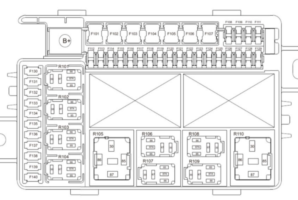
Designation
| F101 | Reserved |
| F102 | 30A (Left window) – Left power window |
| F103 | Reserved |
| F104 | Reserved |
| F105 | 20A (KBCM6) – Body control module 6 |
| F106 | 40A (Front blower) – Front heater blower |
| F107 | 30A (Right window) – Right power window |
| F108 | 5A (Rainfall and light sensor) – Rain and light sensor |
| F109 | 10A (combination instrument) – Instrument cluster |
| F110 | Reserved |
| F111 | 25A (DDCM) – Driver door control module |
| F112 | 10A (Interior lamp) – Interior lamp/light |
| F113 | 25A (Left power seat) – Left power seat (driver) |
| F114 | 20A (IG1) – Ignition 1 |
| F115 | 20A (KBCM7) – Body control module 7 |
| F116 | 20A (KBCM1) – Body control module 1 |
| F117 | 20A (KBCM3) – Body control module 3 |
| F118 | 20A (KBCM4) – Body Control Module 4 |
| F119 | 20A (KBCM5) – Body Control Module 5 |
| F120 | 20A (KBCM2) – Body Control Module 2 |
| F121 | 25A (PDCM) – Passenger Door Control Module |
| F122 | 10A (IG2) – Ignition 2 |
| F123 | 10A (Tester Interface) – Diagnostic Connector (Tester Interface) |
| F124 | 5A (Door switch) – Door switch |
| F125 | 25A (ACC power supply) – Accessory power supply (ACC) |
| F126 | 10A (ESCL) – Electronic steering column lock |
| F127 | 25A (Sunroof) – Sunroof (sun roof) |
| F128 | 25A (Right power seat) – Right power seat (passenger) |
| F129 | 20A (KBCM8) – Body control module 8 |
| F130 | 10A (ABM) – Air bag module |
| F131 | 10A (Parking controller) – Parking sensors / parking controller |
| F132 | 10A (IG1-1) – Ignition 1, circuit 1 |
| F133 | 10A (IG1-2) – Ignition 1, circuit 2 |
| F134 | 5A (Air purifier) - Air purifier |
| F135 | 15A (Spare power supply (b)) – Spare power supply (b) |
| F136 | 15A (Steering wheel heating) – Heated steering wheel |
| F137 | 10A (Air conditioner) – Air Conditioner |
| F138 | 15A (Amplifier 1/HUT) – Amplifier 1 / Head Unit |
| F139 | 5A (T-BOX) – Telematics Unit |
| F140 | 15A (Amplifier 2) – Amplifier 2 |
| R101 | Reserved |
| R102 | Power-saving relay |
| R103 | Reserved |
| R104 | IG1 relay – Ignition relay IG1 |
| R105 | Reserved |
| R106 | Reserved |
| R107 | Reserved |
| R108 | IG2 relay – Ignition relay IG2 |
| R109 | ACC relay – Accessory relay |
| R110 | Front blower relay |
Engine compartment
In the engine compartment, the fuse box is located on the right side, next to the battery.
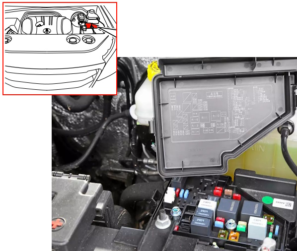
Check the purpose of the elements with your diagrams on the back of the block covers.
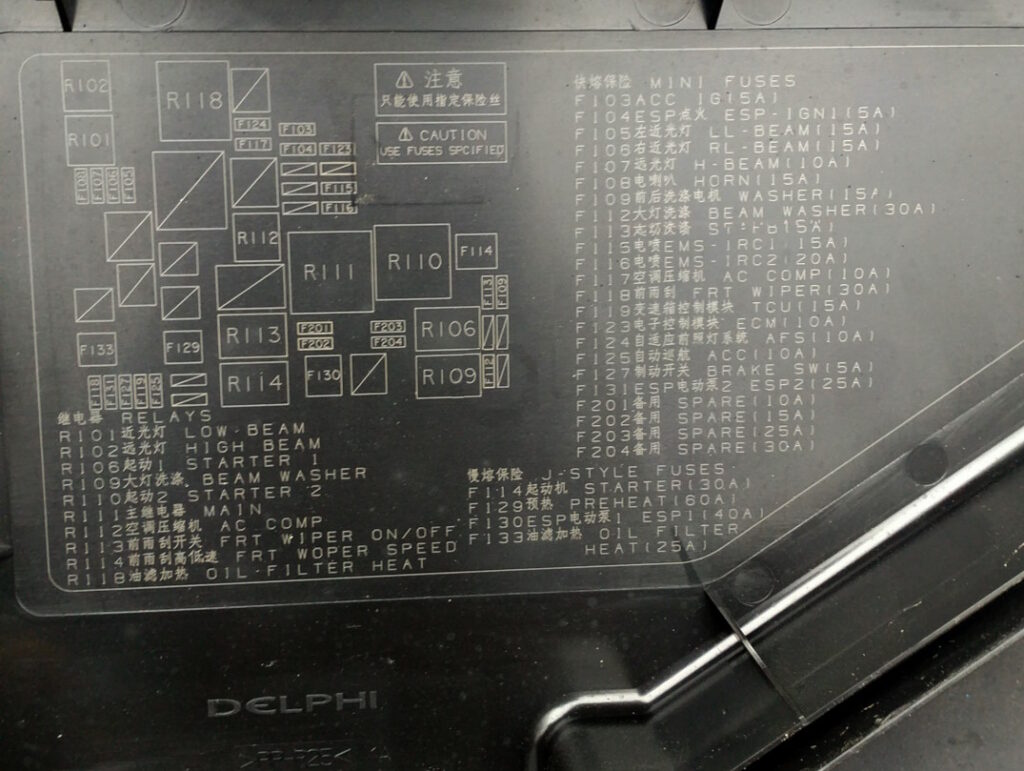
Diagram
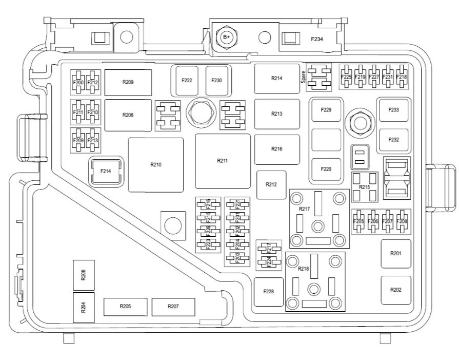
Allocation
| F200 | Reserved |
| F201 | Reserved |
| F202 | Reserved |
| F203 | 5A (ACC) – Accessories |
| F204 | Reserve |
| F205 | 10A (Left combination headlamp) – Left combination headlamp |
| F206 | 10A (Right combination headlamp) – Right combination headlamp |
| F207 | 10A (High beam lamp) – High beam |
| F208 | 15A (Horn) – Horn |
| F209 | 15A (Washer motor) – Headlamp/windshield washer motor |
| F210 | Reserved |
| F211 | Reserved |
| F212 | Reserved |
| F213 | 5A (ST-FB) – Starter (signal) / Feedback |
| F214 | 30A (Starter) – Starter (main) |
| F215 | 15A (Main relay 1) – Main relay 1 |
| F216 | 20A (Main relay 2) – Main relay 2 |
| F217 | 10A (Compressor) – Air conditioning compressor |
| F218 | 30A (Front wiper) – Front Wiper |
| F219 | 15A (TCU) – Transmission Control Module |
| F220 | Reserved |
| F221 | Reserved |
| F222 | 40A (ESP2) – Electronic Stability Program (ESP) Circuit 2 |
| F223 | 10A (ECM) – Engine Control Module |
| F224 | Reserved |
| F225 | Reserved |
| F226 | Reserved |
| F227 | 5A (Brake Switch) – Brake Light Switch |
| F228 | Reserved |
| F229 | Reserved |
| F230 | 60A (ESP1) – Electronic Stability Program (ESP) Circuit 1 |
| F231 | Reserved |
| F232 | Reserved |
| F234 | 100A (ESP) – Electronic Stability Program (ESP) |
| R201 | Low Beam Lamp Relay |
| R202 | High Beam Lamp Relay |
| R204 | Front Washer Relay |
| R205 | Rear Washer Relay |
| R206 | Starter Relay 1 1 |
| R207 | Front axle control 4WD relay |
| R208 | Front axle control 2WD relay |
| R209 | Reserved |
| R210 | Starter relay 2 |
| R211 | Main relay |
| R212 | Compressor relay |
| R213 | Wiper switch relay |
| R214 | Wiper high-speed and low-speed relay |
| R215 | Reserved |
| R216 | Reserved |
| R217 | Reserved |
| R218 | Reserved |
A high-power fuse block in the form of fusible links can be mounted on the positive terminal of the battery.
Luggage compartment
In the luggage compartment, the fuse and relay box is located inside the left or right wall of the luggage compartment.
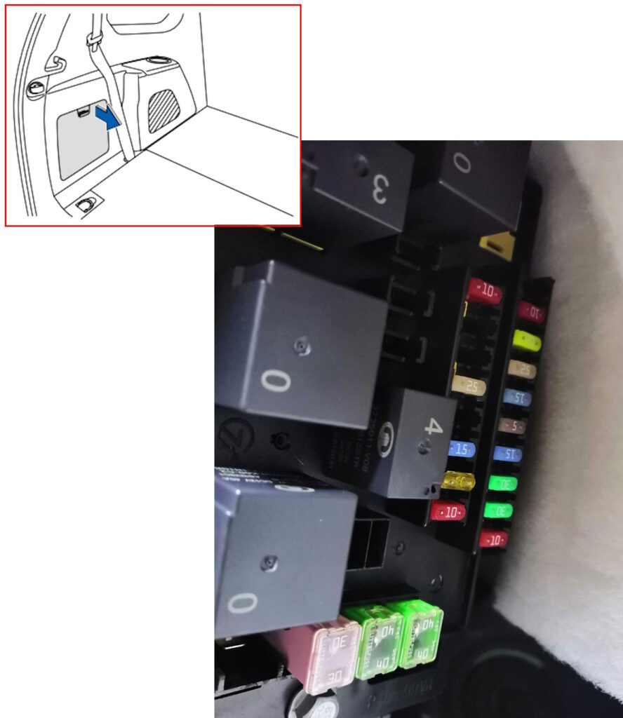
Diagram from covery
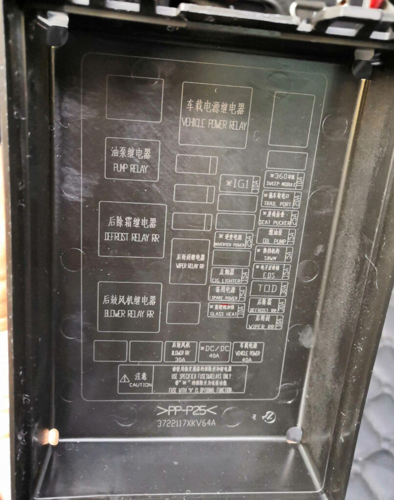
Diagram
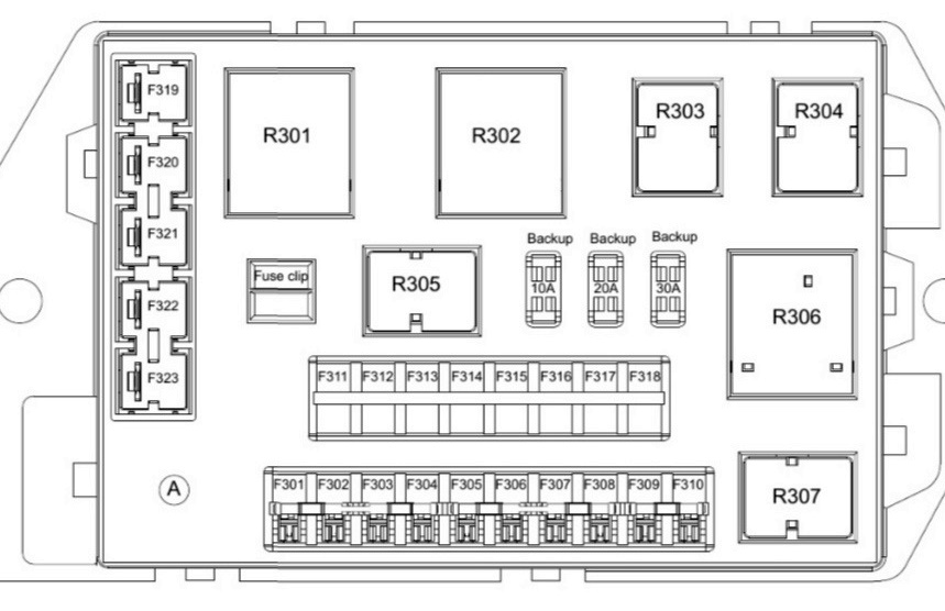
Description
| F301 | 30A Rear Fan |
| F302 | 40A DC/DC Inverter |
| F306 | 40A On-Board Power Supply |
| F307 | 10A Rear Window Wiper |
| F308 | 30A (Rear Window Defogger) – Rear Window Defogger |
| F309 | 30A (TOD) – Transfer Case/4WD |
| F310 | 10A Heated Windshield |
| F311 | 15A Electronic Differential Lock Control Module |
| F312 | 25A Seat Folding Power |
| F313 | 15A Power Socket |
| F314 | 10A IG1 – Ignition IG1 |
| F316 | 25A Inverter, 220V |
| F317 | 20A Trailer Socket |
| F318 | 15A Oil Pump |
| F319 | 15A Cigarette Lighter |
| F320 | 10A Surround View Camera System |
| F321 | 5A Switch Mechanism |
| R302 | On-Board Power Supply Relay |
| R303 | Rear Fan Relay |
| R304 | Rear Window Wiper Relay |
| R307 | Rear Window Defogger Relay |
| R308 | Fuel Pump Relay |
We have a video on this topic on our channel, watch and subscribe.