The 7th generation Volkswagen Golf has been produced from 2012 to the present. Years of production 2013, 2014, 2015, 2016, 2017, 2018, 2019, 2020. Available with hatchback and station wagon bodies with turbo petrol and turbo diesel engines. In this publication, we will show where the fuse and relay boxes are located in the Volkswagen Golf 7, as well as their photos and diagrams with a designation of the purpose of the elements. Note the fuse responsible for the cigarette lighter. At the end of the material you can download the Golf 7 electrical equipment manual. If you own the previous generation of the model, then read its description: Golf 6 .

The purpose of some elements in the diagrams may differ from the one presented and depends on the year of manufacture, configuration and country of delivery. In case of difficulty, contact your nearest dealer.
Passenger compartment
It is located behind the glove compartment on the driver’s side. To access, pull firmly on the left side in the direction of the arrow.
 Photo for example

Next to it is the onboard supply control unit.
Diagram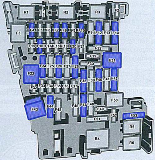
Assignment
| F1 | – |
| F2 | – |
| F3 | – |
| F4 | 10A Onboard supply control unit, Anti-theft system (7.5A) Infotainment control panel |
| F5 | 5A Data bus onboard diagnostic interface |
| F6 | 5A Anti-theft system sensor |
| F7 | 10A Heating and air conditioning regulators, Heater control module, Climatronic control unit, Air conditioning control module, Automatic transmission selector lever, Auxiliary radiator for the engine coolant heater, Heated rear window relay, Frequency receiver |
| F8 | 10A Rotary light switch, Electromechanical parking brake button, Moisture, rain and light sensor, Diagnostic connection |
| F9 | – |
| F10 | 10A Display Control |
| F11 | 10A Four-wheel drive control module |
| F12 | 20A Information Electronics Control Module, Infotainment Components |
| F13 | 15A Electronic damping control module |
| F14 | 30A Supply air fan control module |
| F15 | 10A Electronic steering column lock control unit |
| F16 | 7.5A Amplifier 2-way mobile signal (phone), Antenna amplifier, Voltage converter for USB charging module |
| F17 | 5A Instrument Cluster Control Module |
| F18 | 7.5A Rearview camera, Rear cover unlock switch |
| F19 | 7.5A Access / start system interface |
| F20 | 15A Seat adjustment |
| F21 | – |
| F22 | – |
| F23 | 40A Onboard supply control unit, headlight and exterior lighting |
| F24 | 30A Power sunroof control module |
| F25 | 30A Driver and Passenger Door Control Module |
| F26 | 20A Onboard supply control unit, 30A Heated front seat |
| F27 | 30A Digital sound system control module |
| F28 | 20A Trailer control module |
| F29 | – |
| F30 | 25A Seat belt pretensioner control module |
| F31 | 40A Onboard supply control unit, headlight and exterior lighting |
| F32 | 7.5A Front Camera Driver Assistance System, Remote Control Control Module, Parking Assist System Control Module, Parallel Parking Control Module |
| F33 | 5A Airbag control module |
| F34 | 7.5A Light switch, Interior rearview mirror, Tire pressure monitoring indicator button, Reversing light switch, Air quality sensor, Electromechanical parking brake button |
| F35 | 10A Diagnostic socket, Automatic dimming of the interior rearview mirror, Headlamp leveling and high beam adjustment, Headlamp leveling motor |
| F36 | 10A Daytime running light and parking lights and their control module – right |
| F37 | 10A Daytime running light and parking lights and their control module – left |
| F38 | 20A Trailer control unit |
| F39 | 30A Front passenger door control module, rear right glass motor, driver’s door control module, left rear window regulator motor |
| F40 | 20A Cigarette lighter, 12V socket |
| F41 | 10A Steering column electronics control unit |
| F42 | 40A Onboard supply control unit, Windscreen washer, Central locking |
| F43 | 30A Onboard supply control unit |
| F44 | 15A Trailer control module |
| F45 | 15A Seat adjustment, driver and passenger |
| F46 | – |
| F47 | 15A Rear window wiper motor |
| F48 | – |
| F49 | 5A Clutch pedal position sensor, starter relay |
| F50 | – |
| F51 | 25A Right front seat belt pretensioner control module |
| F52 | – |
| F53 | 30A Heated rear window |
The fuse number 40, 20A, is responsible for the cigarette lighter.
- R1 Relay for reducing agent dosing system -J963-
- R2 –
- R3 –
- R4 Terminal 15 power supply relay -J329-
- R5 Heated rear window relay -J9-
- R6 Socket relay -J807-
Engine compartment
It is located on the left side of the engine compartment, next to the battery and is covered by a protective cover.
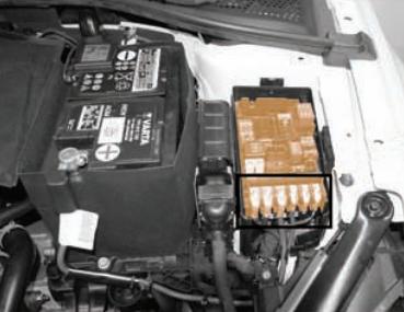
Photo for example

Diagram
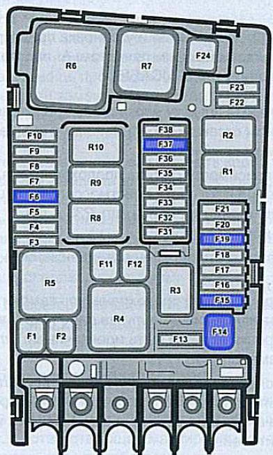
Appointment
| F1 | 40A ABS control unit |
| F2 | 40A ABS control unit |
| F3 | 15A Engine control module |
| F4 | 5A Oil Level Thermal Sensor, Oil Pressure Regulating Valve, Thermal Power Relay, Intake Camshaft Regulator, Ethanol Concentration Sensor |
| F5 | 10A Valve for pressure regulator and fuel metering |
| F6 | 5A Brake light switch |
| F7 | 735A Fuel pressure regulator valve, Cooling circuit solenoid valve, Charge air cooling pump 10A Heater support pump |
| F8 | 10A oxygen sensor |
| F9 | 5A Ignition coil 20A Early evaporation heating element |
| F10 | 15 / 20A Fuel pump control module |
| F11 | 40A Heating element for auxiliary heater |
| F11 | 40A Heating element for auxiliary heater |
| F12 | 40A Heating element for auxiliary heater |
| F13 | 30A Gearbox |
| F14 | 40A Heated windshield |
| F15 | 15A Sound signal |
| F16 | – |
| F17 | 7.5A Engine control unit Motronic, power relay, ABS |
| F18 | 5A Battery control module, data bus onboard diagnostic interface |
| F19 | 30A Wiper Motor Control Module |
| F20 | 20A Anti-theft system, signal |
| F21 | – |
| F22 | 5A Engine control module |
| F23 | 30A Starter |
| F24 | 40A Heating element for auxiliary heater |
| F25 | – |
| F26 | – |
| F27 | – |
| F28 | – |
| F29 | – |
| F30 | – |
| F31 | 15A Brake vacuum pump |
| F32 | – |
| F33 | – |
| F34 | – |
| F35 | 7.5A Air conditioning relay |
| F36 | – |
| F37 | 20A Auxiliary heater control module |
| F38 | – |
Relay
- R1 Starter relay 1 -J906-
- R2 Starter relay 2 -J907-
- R3 Horn relay -J413-
- R4 High heat output relay -J360-
- R5 Main relay -J271- (petrol) / Terminal 30 power supply relay -J317- (diesel)
- R6 Glow control control unit -J179- (petrol)
- R7 Low heat output relay -J359- (diesel)
- R8 Power supply relay for engine components -J757- (2.0l petrol engine)
- R9 Heated windshield relay -J47-
- R10 Heated windscreen relay 2 -J611-
Check out our YouTube video for more on this topic. Don’t forget to subscribe!
I need the numeric fuse assignment for a 2017 Golf Alltrack rear hatch lock.
What does the r4 relay control? Doesn’t say anywhere on this page about relays . Just fuses
Was this not what you wanted just above the comments and below the other info… Also at the top of document, try clicking on OPEN for the PDF ..
Relay
R1 Starter relay 1 -J906-
R2 Starter relay 2 -J907-
R3 Horn relay -J413-
R4 High heat output relay -J360-
R5 Main relay -J271- (petrol) / Terminal 30 power supply relay -J317- (diesel)
R6 Glow control control unit -J179- (petrol)
R7 Low heat output relay -J359- (diesel)
R8 Power supply relay for engine components -J757- (2.0l petrol engine)
R9 Heated windshield relay -J47-
R10 Heated windscreen relay 2 -J611-
Hello.
Do you have also the assignment of the Relays? Because here only the fuses are described. I am interested in the relay for start and for diesel pump command where it is. Thanks.
Is there a fuse or fusible link on the charging circuit
HI,
which is the relay for the fuel pump?