Volkswagen Transporter T4 – represents the 4th generation of the legendary Transporter series. This model was produced in 1990, 1991, 1992, 1993, 1994, 1995, 1996, 1997, 1998, 1999, 2000, 2001, 2002 and 2003 with diesel and gasoline engines with different wheelbases: short and long, and with different roof height. Also on the T4, Volkswagen continued its lineup of luxury Caravelle, California and Multivan models. In our material, we will show the location of all electronic control sides and a detailed designation of the purpose of fuses and relays Volkswagen T4 with box diagrams in which they are located and their photographs. Note the fuse responsible for the cigarette lighter.
The actual purpose of the fuses may differ from the one presented and depends on the year of manufacture and the level of electrical equipment T4 .
Contents
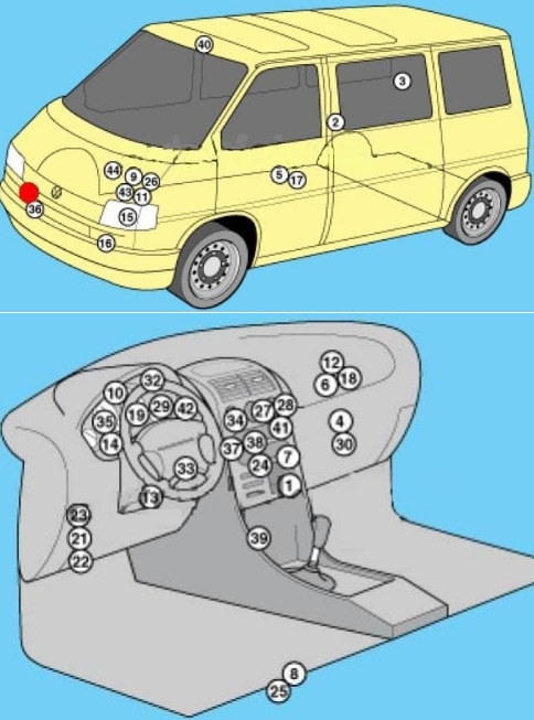
Locations
Diagram
Description
| 1 | Air conditioning control unit 1 – with automatic temperature control – in the heater control panel, front |
| 2 | Air conditioning control unit 2 – with automatic temperature control – in the heater control panel, rear – central pillar |
| 3 | Evaporator Fan Control Unit (A / C) – With Rear A / C – Behind Right Rear Trim Panel |
| 4 | Air conditioning / heater fan motor control unit 1 – with automatic temperature control – front – fan unit |
| 5 | Air conditioning / heater blower motor control unit 2- with automatic temperature control – rear- bottom of the body, in the center |
| 6 | Aerial amplifier – behind the dash, passenger side |
| 7 | Alternator resistor – near additional relays – CV / AUF, with alternator 150A / automatic transmission / automatic temperature control – behind the central part of the dashboard |
| 8 | Additional battery – under the driver’s seat |
| 9 | Accumulator battery |
| 10 | Central locking signal control unit – behind the dashboard |
| 11 | Cruise control unit (with throttle motor) – cruise control is controlled by the ECM |
| 12 | Electronic cruise control module (without throttle motor) – behind dash, passenger side |
| 13 | Diagnostic connector (DLC) – instrument panel, driver’s side |
| 14 | Diagnostic unit – 05/99 (except for AAC / ABL / AET / AES / AJA) – in the instrument cluster |
| 15 | Cooling Fan Motor Relay – Behind Left Headlight |
| 16 | Cooling Fan Motor 1/2 Resistor – Behind Left Headlight |
| 17 | Coolant heater control unit (with additional coolant heater – D3W / B4W / D4W) – in the heater – underbody, in the center |
| 18 | Coolant heater control unit (with optional coolant heater – B7W / D7W) – behind the dash, passenger side |
| 19 | Engine oil pressure warning buzzer – in instrument cluster control unit |
| 21 | Fuse / relay box, instrument cluster 1 |
| 22 | Fuse / relay box 2, dash – under dash fuse / relay box 1 |
| 23 | Fuse / relay box, dash 3 – above dash fuse / relay box 1 |
| 24 | Fuse / relay box, dash 4 – behind dash, center |
| 25 | Fuse / Relay Box, Driver’s Seat – Under Seat |
| 26 | Fuse / Relay Box, Engine Compartment – Battery Powered |
| 27 | Additional fuse (5A / 7.5A / 10A) – in the back of the audio system unit |
| 28 | Additional fuse (10A) – at the rear of the navigation system control unit |
| 29 | Headlights not switched off warning buzzer – in the instrument cluster control unit |
| 30 | Heater blower motor resistor – manual temperature control – blower unit, front |
| 31 | Horn 1/2 – behind the front bumper |
| 32 | Immobilizer control unit – behind the instrument cluster |
| 33 | Immobilizer ring antenna – near the ignition switch |
| 34 | Turn signal relay, alarm relay – in the alarm switch |
| 35 | Instrument Cluster Control Module / Digital Multifunction Display – In Instrument Cluster |
| 36 | Outside temperature sensor – behind the front bumper |
| 37 | Driver’s seat heating control unit – in the seat heating switch |
| 38 | Passenger seat heating control unit – in the seat heating switch |
| 39 | SRS control unit – under the dash, center |
| 40 | Sunroof electric control unit |
| 41 | Theme control unit – in the display of the navigation system |
| 42 | Telephone interface control unit – behind the instrument cluster |
| 43 | Electronic gearbox control unit – near the engine control unit |
| 44 | Vehicle speed sensor – gearbox |
Passenger compartment
The main fuse and relay box is located under the dash on the driver’s side.
Main box
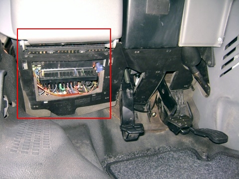
Photo for example
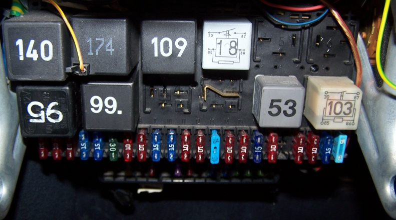
Diagram
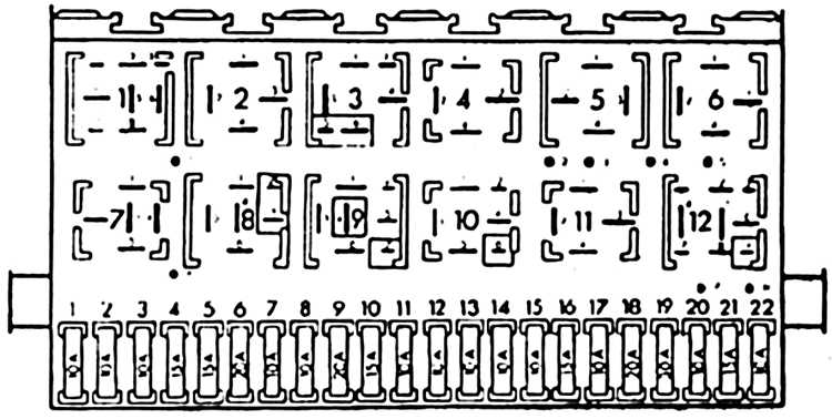
Relay assignment
- (105) Heater blower motor relay – rear (ventilation)
- (174) Rear window wiper / washer relay
- (30/109) Engine management relay
- (18) Ignition auxiliary circuits relay 1
- Reserve
- (22/21) Emergency ventilation relay (with repeaters for direction indicators on the roof)
- (95) Headlight washer pump relay
- (99) Relay for intermittent operation of the windshield wiper / washer
- (36) Headlamps warning buzzer
- (53) Fog lamp relay
- (53) Horn relay
- (167) Fuel pump relay
Fuse
| 1 | 10A Left headlight – low beam, headlight range control |
| 2 | 10A Right headlight – low beam, headlight range control |
| 3 | 10A License plate lamps |
| 4 | 15A Rear window wiper / washer, auxiliary ignition circuit relay 2, additional equipment |
| 5 | 15A / 20A Windshield wiper / washer, heaters for windshield washer nozzles (05/01) |
| 6 | 30A Air conditioning system, heater fan motor |
| 7 | 10A Front right side / rear right side lamps |
| 8 | 10A Lamps front left / rear left |
| 9 | 20A Heated rear window, heated outside mirror |
| 10 | 15A Fog lights, fog lights |
| 11 | 10A left headlamp-high beam |
| 12 | 10A RH headlamp-high beam |
| 13 | 10A Sound signal |
| 14 | 10A ABS system (with ESP), automatic transmission control system, additional equipment, central locking, cruise control system, power windows, power rear-view mirrors on the doors, reverse light (s) |
| 15 | 10A Engine management system, crankcase ventilation heater, cruise control system, vehicle speed sensor |
| 16 | 15A ABS indicator, glove box illumination lamp, turn signals, immobilizer, instrument cluster |
| 17 | 10A Additional heater |
| 18 | 20A Engine management system, fuel pump |
| 19 | 10A Cooling fan motor control unit, coolant pump motor |
| 20 | 10A Stop lights |
| 21 | 15A Audio system, diagnostic connector (DLC), interior lamps, navigation system |
| 22 | 10A Cigarette lighter fuse, radio |
The fuse number 22, 10A, is responsible for the cigarette lighter.
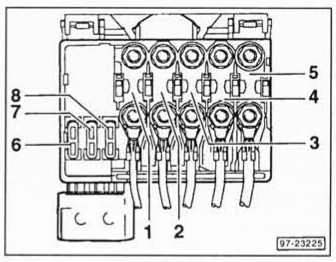
Additional fuse box
It is located under the main block.
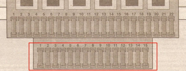
Designation
| 1 | 15A Accessory power connector |
| 2 | 15A Trailer electrical connector |
| 3 | 10A Roof identification light |
| 4 | 20A Additional heater (AC V / AH Y / AJT / AU F) |
| 5 | 10A Anti-lock braking system (ABS) |
| 6 | FOR Phone |
| 7 | 15A Taxi |
| 8 | 10A Roof fan |
| 9 | 15A Audio system, instrument cluster |
| 10 | 15A Central locking |
| 11 | 15A Heated seats |
| 12 | 30A Heated door mirrors, heated rear window |
| 13 | FOR PHONE (ACV / AH Y / AJT / AU F) |
| 14 | 30A Air conditioning system – manual automatic temperature control |
| 15 | 20A Additional heater |
Additional relay box 1
Located at the top of the main unit.
Diagram
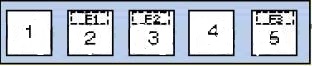
Assignment
| 1 | (53) Coolant pump relay |
| 2 | (125) Idle speed control (AM) relay |
| 3 | (137) Glow plug control unit (ABL) |
| 4 | (53) Ignition auxiliary circuits relay 2 (some models) |
| 5 | (53) Ignition auxiliary circuits relay 2 (AES, with air conditioning) |
| F1 | (30) Power window fuse |
| F2 | (15) Engine control unit |
| F3 | (15) Actuator |
Additional relay box 2
It is located behind the dashboard in the center.
Diagram
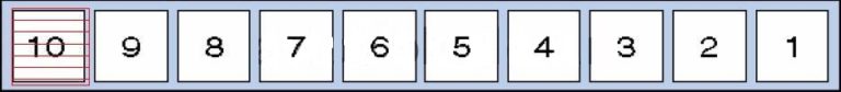
Designation
| 1 | (106) Auxiliary heater relay |
| 2 | Audio / Telephone Speaker Switch Relay |
| 3 | (53) Heater blower motor relay – rear (warm air) |
| 4 | (114) Heater blower motor relay – automatic temperature control |
| 5 | (152) Heater radiator coolant valve relay (rear heater) |
| 6 | (38) Air intake changeover actuator relay (A / C / heater) |
| 7 | (53) Alternator relay (AES, with 150A alternator) |
| 8 | (53) Alternator relay (ACV / AUF, with alternator 150A / automatic / automatic temperature control) |
| 9 | (175) Start inhibit switch relay / reversing lamp relay |
| 10 | (87) Wheel hub connection control unit |
Another unit can be located under the driver’s seat. The following items may be located there: (214/426) Relay for additional battery, (403) Relay for additional heater, (30A) Additional liquid heating system, (5A) Sockets , etc.
Engine compartment
This unit is located on the cover in front of the battery.
Diagram
Protected components
| 1 | 60A Glow plug relay |
| 2 | 50A Cooling fan motor |
| 3 | 50A Cooling fan motor |
| 4 | 50A Anti-lock braking system (ABS) |
| 5 | 110A / 150A / 175A generator |
| 6 | 30A System of maintaining exchange rate stability |
| 7 | 30A Anti-lock braking system (with ESP) |
| 8 | 5A System of maintaining exchange rate stability |
We have posted a video on our YouTube channel. Watch and subscribe.
Still have questions? Ask them in the comments.
thank you,
VW 1998 2.4 DIESEL CARAVELLE. LAYOUT AS ABOVE IS SOMEWHAT DIFFERENT FOR MY VW,
TRYING TO LOCATE IF THERE IS ONE FITTED, LOW/HIGH BEAM RELAY. As intermittent fault occurring . (S121LCK)
Much appreciated feedback.
william
Hi
I have a volkeswagen T4 1998.model and I have a light problem , I went to fit a toggle switch but tried the lights now don’t work .
Hi
do you offer pdf ?
i have a 1998 Vw T4 westfalia LHD
2.5TDi ACV ENGINE
Re: 1997 VW EuroVan Camper
2.8L -V6
Could you please provide me with the relay designations for the above mentioned VW Vehicle
or direct me where I can find it for that exact year, make and model. Thanking you in advance.
Eddie
Hello,
In my CARAVELLE t4 from. 2001 I need to temp disable all airbags, in the fuse schematics I can’t find any fuse description to deactivate/pull the system… How to do this without removing all components from the dash and steering wheel? (Including deactivation of of the warning lights..)
Thx, ernst
I don’t know for sure Ernst, but I suspect airbags don’t really need to be fused. Would you want your airbag to fail to detonate if the chemical igniter used 12A instead of 10A and blew a fuse? 🙂 I opened my wheel horn button up to find no airbag at all, so luckily I don’t have this problem.
buenas tardes de sharan 2005 motor 1.8 turbotendran informacion gracias
I have short circuited the alternator on my 1997 VW t4 Caravelle VR6
The underbonnet fuses are not as per your picture I cannot find the 110A / 150A / 175A generator can any help further ?
Thanks
I have a 1997 eurovan, the problem I have is, the cigarette lighter and the 110 power plug above the fridge don’t work. Could you direct me where the fuses are? and also the same plugs at the back of the van have no power either. I appreciate any help.
Yesterday I turned off the motor of my 2000 T4 2.5tdi (ACV) at a long light. When I tried to start it again, nothing, no clicks, nada. All the dash lights came on as usual. Had the car towed home after many many attempts. This morning I went to address the problem, it started first time and continues to do so consitently. Any ideas?
I was having some trouble with the battery going flat over night, did a leakage test (ran battery through a multimeter on 0.5A fuse) and found the car used around 45mA when parked. This isn’t great, but it isn’t bad by modern standards, the battery is a bit small and old that’s my real problem, but I thought i’d pull fuses to see what’s using the juice. Your diagrams really helped me figure it out. Seems for me it’s the two power windows have a high idle current of 20mA, and the trailer-hitch power plug (or wires in that system) in my van are leaking about 20mA, probably a insulation issue 5omewhere + water. Pulling those two fuses gets the total power down to just 0.9mA, and if I pull fuse 21, which for me is the instrument cluster, it drops to 0mA, or undetectable by my meter! So a T4 with those fuses pulled will still lock/unlock, but the windows wont work, the cluster wont power the odometer screen, but the battery will take *much* longer to go flat. Thinking about putting a 3P1T switch on those wires to flip it into hibernation mode without having to pull the fuses.