Volkswagen Touareg is a mid-size crossover that has been produced in 3 generations from 2002 to the present with both gasoline and diesel engines. Years of production of the first generation: 2003, 2004, 2005, 2006, 2007, 2008, 2009 and 2010. During this time, the car received a facelift. In our material you will find a designation of fuses and relays Volkswagen Tuareg 1st generation with photos and boxes diagrams in which they are located. Separately, we note the fuse responsible for the cigarette lighter.

The purpose of the elements in your boxes may differ from the one presented and depends on the year of manufacture and the level of electrical equipment of the car.
Contents
Location
The locations where the main boxes with fuses and relays are located are shown in these figures.
Layout


Passenger compartment
Left side box
To access, remove the protective cover from the left end of the instrument panel.

Photo for example

Diagram

Assignment
A – spare fuses
| 1 | 20A Cigarette lighter |
| 2 | 5A Parking heating (clock, sensor, pump) 15A Circulation pump relay |
| 3 | 20A Additional sockets (12V) |
| 4 | 20A Parking heating – heater |
| 5 | 20A Socket relay |
| 6 | 15А KESSY |
| 7 | 5A Diagnostics, multiplex system, rain and light sensor |
| 8 | 30A Wipers |
| 9 | 15A Glass washer pump |
| 10 | 25A Window Regulator – Left Rear |
| 11 | 15A Central locking – left |
| 12 | 20A Interior lighting |
| 13 | – |
| 14 | 25A Window Regulator – Left Front |
| 15 | 20A Left rear lamp |
| 16 | 20A Sound signal |
| 17 | 10A Direction indicator, parking lights – left |
| 18 | 20A Relay SRA |
| 19 | 15A Fog lights |
| 20 | 30A Electric seat |
| 21 | 15A Additional turning headlight |
| 22 | 30A Lateral locking, trunk lid control unit 2 |
| 23 | 10A Rear transverse locking |
| 24 | 5A Tire pressure monitoring system |
| 25 | 15A Steering column adjustment – electro |
| 26 | 10A Airbag control unit, Front passenger airbag deactivation, clutch pedal switch |
| 27 | 5A Switch for turning off the interior monitoring system, interior lighting |
| 28-32 | Reserve |
| 33 | 15A Steering wheel heating, steering column control unit |
| 34 | 5A Heated seat sensor, Security monitoring of the interior |
| 35 | 15A Dipped beam, high beam 30A Onboard supply control unit |
| 36 | 10A Powered by on-board battery |
| 37 | – |
| 38 | 10A Brake signals |
| 39 | 5A Relay for ignition system, air conditioning, seat heating, instrument panel |
| 40 | 5A Instrument panel |
| 41 | 15А KESSY |
| 42 | 30A Electro hatch |
| 43 | 30A Subwoofer |
| 44 | 30A Electro seat device |
| 45 | 30A Electro seat device |
| 46 | – |
| 47 | 10A Cross-axle differential lock control unit |
| 48 | 5A Parking heating clock, lane change assist control unit |
| 49 | 5A Servotronic |
| 50 | 10A Oil level and temperature sensor, Blowing heater pipe (VR6) |
| 51 | 5A Air Quality Sensor, Tire Pressure Monitoring System, Diagnostics |
| 52 | 30A Rear wiper |
| 53 | 5A Security surveillance of the interior space of the passenger compartment, External lighting switching unit, Heated mirrors |
| 54 | 10A Headlight range control |
| 55 | 15A supply fan relay (speed 2) |
| 56 | 40A Climate control |
| 57 | 40A Bitron fan adjustment motor |
The fuses with numbers 1, 3 and 5 for 20A are responsible for the cigarette lighter.
Fuse # 1 is: cigarette lighter + 12v socket in the central tunnel for rear passengers.
Fuse number 3 is: a 12v socket in the luggage compartment (in the wall on the right), the one that is closer to the fifth door.
Fuse No. 5 is: 12v driver’s socket (near the automatic transmission handle) and 12v socket in the luggage compartment (in the wall on the right).
Right side box
Located in the right end of the dashboard, it is also covered with a protective cover.

Diagram
 Designation
| 1 | 15A Trailer Recognition Control Unit |
| 2 | 5A Parktronic, Compass |
| 3 | 15A Trailer control unit |
| 4 | 5A Phone |
| 5 | 15A Trailer recognition control unit |
| 6 | 30A Anti-slip system ESP, ABS |
| 7 | 5A Transfer case control unit |
| 8 | 20A Additional high beam headlamps |
| 9 | 5A CD changer |
| 10 | 5A TV tuner |
| 11 | 10A Radio |
| 12 | 30A Audio Amplifier, Antenna Switch |
| 13 | – |
| 14 | 20A Right rear lamp, 15A trunk lid control unit |
| 15 | 25A Window Regulator – Right Rear |
| 16 | 10A Trunk lighting |
| 17 | 15A Low beam, High beam |
| 18 | 30A Rear window defogger relay |
| 19 | 25 / 30A Traction hitch tilt motor |
| 20 | 30A Electric seat adjustment 20A Inverter with socket, 12V-230V |
| 21 | 10A Security alarm system, Spare wheel unlocking |
| 22 | 25 / 30A Electrically adjustable front right seat, Heated front seats |
| 23 | 10A Climate control |
| 24 | 25 / 30A Electro seat adjustment |
| 25 | 5A Rear climate control console |
| 26 | – |
| 27 | 15A Tire pressure monitoring system, Ride height control control unit |
| 28 | 10A Automatic distance keeping |
| 29 | 10A Automatic transmission (automatic transmission) |
| 30 | 20A Winch, closer relay |
| 31 | 25A Rear control unit, 15A Rear lid control unit |
| 32 | 10A Central locking – right |
| 33 | 10A Rear alarm system control unit 15A Individual equipment |
| 34 | 25A Window Regulator – Right Front |
| 35 | 10A Direction indicator, parking lights, right 30A Control panel for front passenger seat adjustment |
| 36 | 5A Ceiling module, Telephone |
| 37 | – |
| 38 | EPS, ABS |
| 39 | 10A Climate control 5A Relay for windscreen heating element |
| 40 | 10A Longitudinal blocking |
| 41 | 10A Trailer control unit |
| 42 | 5A Radio, Garage door opener control |
| 43 | 5A Reversing light switch |
| 44 | Heated washer jets, seat heating regulator |
| 45 | Reserve |
| 46 | Reserve |
| 47 | 10A Automatic distance control, radar sensor, right headlight module |
| 48 | 10A Air suspension control unit |
| 49 | 5A Mirror, Telephone |
| 50 | 5A Parktronic, switch off ASR and ESP |
| 51 | 20A Gearbox |
| 52 | 5A Selector |
| 53 | 30A Windshield heater relay |
| 54 | 30A Electric trailer brakes, Windshield heater relay |
| 55 | 20A Electric steering column |
| 56 | 40A ABS, ESP |
| 57 | 40A Longitudinal blocking |
Box under the driver’s seat

Located on or near the battery cover.

Diagram

Protected components
- Main battery switch
- Power supply relay terminal 15 (100) / (433)
- Second battery charging relay
| SD1 | 150A Left fuse box |
| SD2 | 150A Right fuse box |
| SD3 | 60A Right fuse box |
| SD4 | 60A Switching block, left fuse box |
| SD5 | 60A Terminal 15 relay |
| SD7 | 250A Parallel connection of the battery |
| SD8 | 150A Socket |
| SD9 | 5A Onboard supply control unit |
| SD10 | 10A Onboard supply control unit |
| SD11 | 5A Diagnostics of the starter wire |
| SD12 | Not used |
| SD13 | 40A The electric motor of the compressor of the ride height control system |
| SD14 | Not used |
Relay box
It is installed in the lower part of the dashboard, in the area of the steering rack.

Diagram

Description
| D1 | Servotronic control unit (476) |
| D2 | Closer relay (404) |
| D3 | Ride height control compressor relay (373) |
| D4 | Socket relay (404) |
| D5 | Air conditioning relay (100) |
| D6 | Fresh air blower relay, speed 2 (404) only with manual air conditioning |
| D7 | Heated rear window relay (53) |
| D8 | Circulation pump relay (404) VR6 only with auxiliary heater |
| D9 | Alternator connection relay (53) |
| E1 | Solar Cell Isolation Relay (79) |
| E2 | Spare wheel release relay (404) |
| E3 | Left windscreen heater relay (53) |
| E4 | Circulation pump relay (404) |
| E5 | Power supply relay 2 terminal (432) V10 TDI only |
| E6 | Not used |
| E7 | Headlamp cleaning relay (53) |
| E8 | Residual heat accumulator relay (404) |
| E9 | Heated windscreen relay, right (53) |
Engine compartment
This relay and fuse box is located in the air intake compartment of the engine compartment.

For example

Diagram
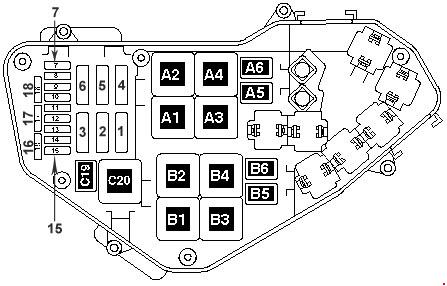
Designation
| 1 | 60A radiator fan control unit, radiator fan |
| 2 | 30A radiator fan control unit, radiator fan |
| 3 | 40A secondary air pump |
| 4 | 40A secondary air pump |
| 5 | 30A ignition coil, fuses in the relay and fuse box |
| 6 | 30A ignition coil |
| 7 | 10A Cylinder Injector, Fuel Cooling Pump Relay 20A Ignition Coil |
| 8 | 10A injector cylinder 20A ignition coil |
| 9 | 30A Motronic control unit, engine control unit, diesel injection control unit |
| 10 | 10A high pressure sensor, air mass meter, air conditioning control unit, alternator connection relay, auxiliary cooling pump relay, brake booster relay (3.2 l), fuel system diagnostic pump, turbocharger control unit |
| 11 | 15A oil level and temperature sensor, Climatronic control unit, absorber solenoid valve, turbocharger control unit 10A Air conditioning control unit |
| 12 | 5A secondary air pump relay, electric fuel pump relay 10A absorber solenoid valve 1, regulator, glow plug control unit 20A coolant thermostat electronically controlled engine, high pressure sensor, coolant circulation relay after off. engine, air conditioning control unit, intake camshaft adjuster valve, intake manifold geometry change motor |
| 13 | 15A fuel pressure regulator, fuel pump |
| 14 | 15A fuel pressure regulator, fuel pump 10A fuel metering valve |
| 15 | 15A fuel pump relay, Motronic control unit, engine control unit |
| 16 | 10A parallel battery relay, 30A brake pump |
| 17 | 15A lambda probe 30A lambda probe |
| 18 | 7.5 / 15A lambda probe after catalytic converter |
Relay
| A1 | Glow plug control unit (475) |
| A2 | Terminal 30 power supply relay (109) / (219) |
| A4 | Fuel pump relay (53) |
| A6 | Fuel cooling pump relay (404) |
| A5 | Additional coolant pump relay (404) |
| A3 | Glow plug control unit (475) |
| B6 | Additional fuel pump relay (449) |
| B7 | Not used |
| B4 | Low heating power relay (100) Power supply relay 1 (100) |
| B3 | High power heating relay (100) |
| B1 | Terminal 30 power supply relay (219) |
| B2 | Fuel pump relay (53) |
| C20 | Terminal 50 power supply relay (433) |
| C19 | Fuel boost pump relay (404) |
On our YouTube Channel, we placed video. See and subscribe.
That’s all. If you know how to make the material better – write in the comments.
2005 vw touareg 4.2
What fuse number and location controls left front and back turn signals?
Ignition refuses to come up (no light displaying on my dashboard) hence, car won’t start. I have tried checking and fixing all fuses but to no result.
Though when Key is inserted into the Volkswagen Touareg 2004, I hear it usual ‘Clingy’ sound; telling it’s recognises the key perhaps. Yet the vehicle won’t turn on ignition neither start engine (no single light appears on dashboard)
NB: All light components are working just fine except for the ignition.
What could be the possible problem and solution?
My car had the same symptoms. How did you solve it?
I’m trying to find out where the relay for the horn on a 2012 VW Toureg is located. My horn doesn’t work, and the fuse is OK. Can anyone help please
Eric
el problema lo puedes tener en el anillo del air-bag
Ne radi mi osvjetljenje prostora za noge sve radilo ugasio auto otisao na sastanak vratio se cim vrata otvoris sve se upali samo pod nogama ne i kad upalim auto pod nogama gori ambijentno svijetlo postoji li kakav osigurac ili nesto pomozite mi
Hi my radio,sunroof, indicators and left light not working could it be a relay and if yes which one
Hay
Where is the fuse of boost solonoids of touareg R5 TDI 2006
Thanks
De un volwagen golf espor 2011 2.5 cajas de fusible motor e interior