The Omoda C7 entered production in 2025 and is still in production. It is shipped worldwide. In this article, we will describe the Omoda C7 ‘s fuses and relays, including fuse box diagrams, their locations, and photo examples. We will highlight the fuse responsible for the cigarette lighter and USB ports.
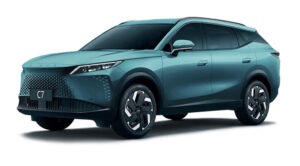
The purpose of fuses and relays may differ from those presented and depend on the year of manufacture, the level of electrical equipment and the region of delivery of your vehicle.
Passenger compartment
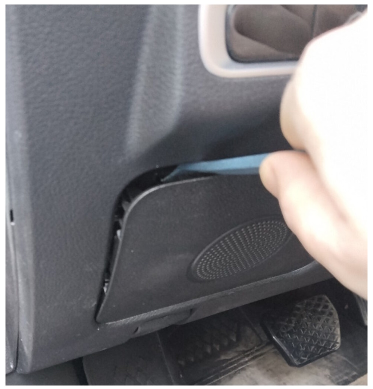
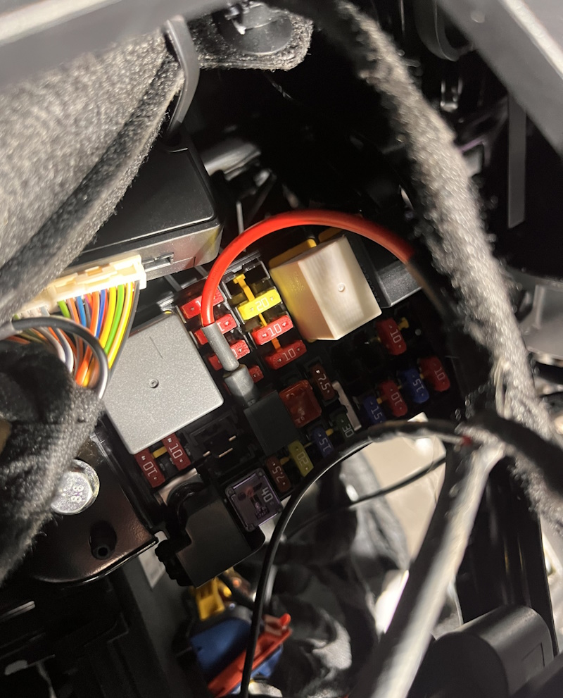
Inside the car, the fuse and relay box is located at the bottom of the instrument panel behind a plastic protective cover.

Or through the protective cover, if there is one on the panel.
Location
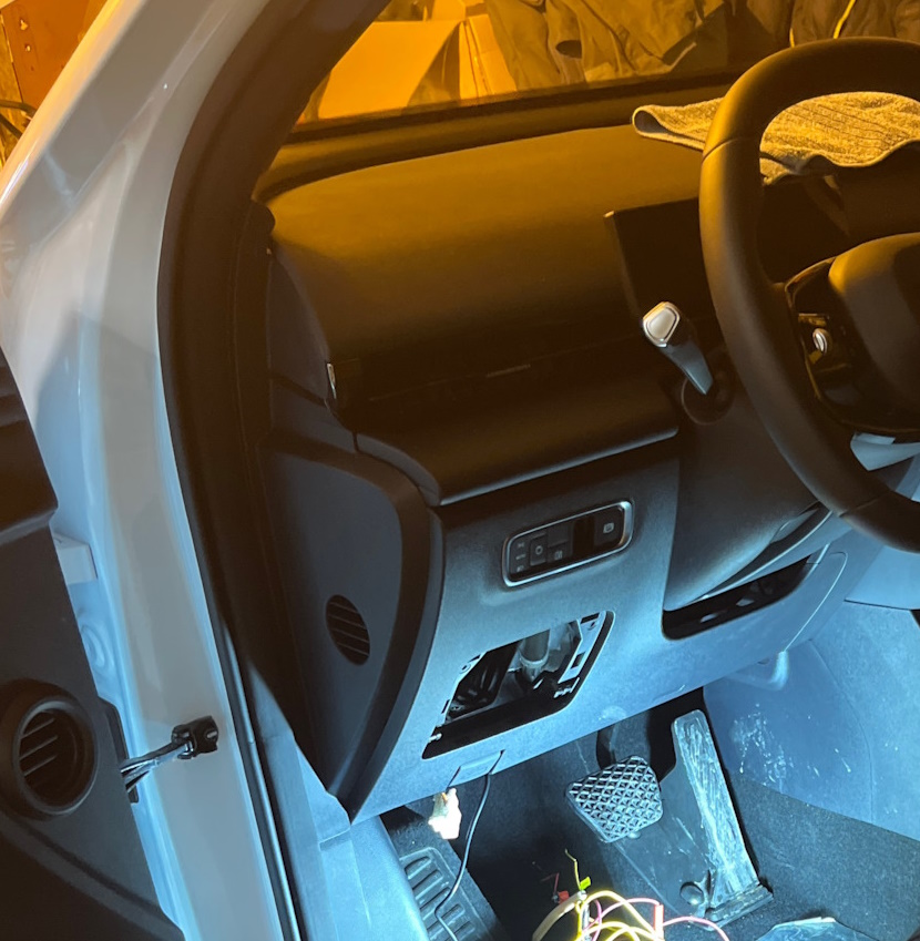
Photo of fuse box
Diagram

Assignment
| RF01 | Comfort unit, panel/instrument cluster control unit, Immobilizer (BCM & ICM & IMMO) |
| RF02 | Reserve |
| RF03 | Steering Angle Sensor, EPS (EPS & SAM) |
| RF04 | Empty or in some trim levels – 360 degree surround view system, blind spot monitoring system, multimedia system, Forward warning radar (AVM & BSD & MPC & MRR) |
| RF05 | Airbags, system control unit (AIR BAG) |
| RF06 | Reserve |
| RF07 | Air Conditioning Control Panel, Head Unit Control Panel, Headlight Leveling Switch Power, ESP Control Switch (SEE NOTE) |
| RF08 | Door lights, panoramic controller, shock sensor, camera and DVR charging port |
| RF09 | Radio, head unit control unit, air conditioner and heater control panel (RADIO & AC & T-BOX) |
| RF10 | Front panel control unit, rain sensor (ICM& Rain Sensor) |
| RF11 | Reserve |
| RF12 | Reserve |
| RF13 | Transmission control unit (CVT25) |
| RF14 | Reserve |
| RF15 | Sunroof, Volume Control, Key Backlight, Monitor Module, Heating Relay Coil (DIAGNOSIS & VTM & KEYIN & EPB SW) |
| RF16 | USB charging unit, usb port (USB POWER) |
| RF17 | Reserve |
| RF18 | Heated power side mirrors (left and right), Heated/heated rear window feedback (MIRROR HEATER) |
| RF19 | PEPS keyless entry and start system, all-wheel drive system, ECU and DC-DC start-stop system (ISS) (PEPS&DC(ISS)) |
| RF20 | Seat adjustment, electric (SEAT ADJ) |
| RF21 | Circuit AM2 when starting the engine (on a car without a PEPS keyless entry system) (IGN SW2) |
| RF22 | Empty or ignition position 1 (IGN SW1) |
| RF23 | Reserve |
| RF24 | Heated rear window, relay 03 (DEFROST) |
| RF25 | Reserve |
| RF26 | Control block head unit, electric mirror adjustment drive, BCM unit, (RADIO & BCM & MIRROR ADJ) |
| RF27 | 15A Cigarette lighter (CIGAR LIGHT) |
| RF28 | Reverse Lamp |
| Relay | |
| RRLY 01 | Reserve |
| RRLY 02 | Reverse Lamp for ISS |
| RRLY 03 | Heated rear window relay (DEFROST) |
The cigarette lighter is controlled by fuse 27 at 15A.
Engine compartment
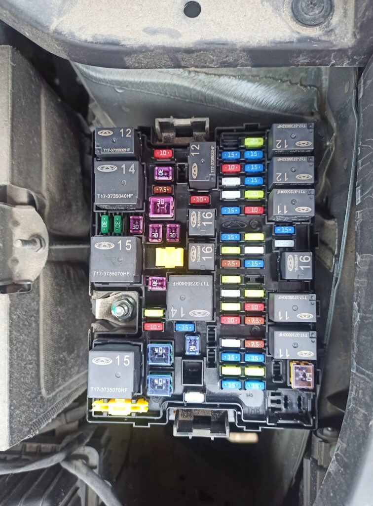
Under the hood, the main block with fuses and relays is located on the left side, next to the battery and is covered with a protective cover.
Photo example
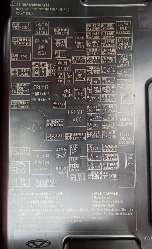
Check the purpose of the elements with your diagram on the back of the block cover.
Diagram
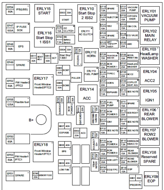
Description
| EF01 | 20A Electric Vacuum Pump |
| EF02 | 15A Electronic Thermostat, Oxygen Sensor, Start-Stop Relay |
| EF03 | 15A Ignition Coils |
| EF04 | 15A Canister Solenoid, Camshaft Position Adjuster, Relief Valve, Oil Pump, Crankcase Ventilation Heater |
| EF05 | 20A All-Wheel Drive System |
| EF06 | 10A Cooling Fan, Brake Booster, Canister Close Valve |
| EF07 | 25A Spare |
| EF08 | 20A ACC2 (Second Accessory Power Circuit) |
| EF09 | 25A Spare |
| EF10 | 15A Start-Stop Configuration, Starter Relay (EARLY15), A/C Compressor Relay, Oil Pump Relay |
| EF11 | 15A Spare |
| EF12 | 20A Right Headlight (Top Equipment) |
| EF13 | 10A Engine Control Unit (ECU), Transmission Control Unit TCU-7DCT380 / TCU-DCT4 / TCU-8AT, All-Wheel Drive Module |
| EF14 | 7.5A ACC Radar, Panoramic Sunroof, Ventilation Seat memory, dash cam, cornering lights |
| EF15 | 7.5A Intelligent Domain Controller (I/FCM), Front Radar Module (FRM) |
| EF16 | 15A Rear Air Conditioner |
| EF17 | 20A Second-row Fan |
| EF18 | 15A Electric Oil Pump (EOP) |
| EF19 | 7.5A Reserve |
| EF20 | 15A Fuel Injectors |
| EF21 | 10A Start-Stop System #2 |
| EF22 | 10A Reserve |
| EF23 | 20A Reserve |
| EF24 | 15A Front and Rear Windshield Wipers |
| EF25 | 15A Power Supply for BCM #1 (Body Control Module) |
| EF26 | 15A USB Type-C Port |
| EF27 | 20A Horn |
| EF28 | 7.5A Electronic Stability Program (ESP), Electronic Parking Brake (EPB), ONE BOX Integrated Brake Module |
| EF29 | 20A Fuel Pump |
| EF30 | 25A Power Supply for BCM #5 (Body Control Module) |
| EF31 | 20A Ignition Circuit IGN1 |
| EF32 | 10A Driver Door Module, Window Switch, Brake Switch, Power Tailgate, Blind Spot Sensor |
| EF33 | 25A Power Supply for BCM #4 (Body Control Module) |
| EF34 | 15A Power Supply for BCM #9 (Body Control Module) |
| EF35 | 20A Left Headlight (Top Equipment) |
| EF36 | 15A Electronic Gear Selector (EGS), Fuel Filter Controller Pump (FPC) |
| EF37 | 15A Rear Backup Power Supply |
| EF38 | 10A Engine Control Unit (ECU), Transmission Control Unit TCU-DCT4 |
| EF39 | 25A Windshield Wiper |
| EF40 | 10A Reserve |
| EF41 | 20A Left Second Row Seat |
| EF42 | 10A A/C Compressor |
| EF43 | 7.5A Battery Sensor |
| EF44 | 30A BCM Power Supply #2 (Body Control Module) |
| EF45 | 30A Panoramic Roof |
| EF46 | 25A Transport Fuse |
| EF47 | 100A Instrument Panel Fuse Box (IP Fuse Box) |
| EF48 | 80A Electric Power Steering (EPS) |
| EF49 | Spare |
| EF50 | 60A Cooling Fan |
| EF51 | 50A Electric PTC Cabin Heater |
| EF52 | 50A Heated Windshield / PTC Heater #2 |
| EF53 | 50A Heated Windshield / PTC Heater #1 |
| EF54 | 60A Integrated Electronic Brake Module (ONE BOX) (Brake-by-Wire) |
| EF55 | 125A Flexible Fuel Mode |
| SB01 | 60A Integrated Electronic Brake Module ONE BOX |
| SB02 | 20A ACC (Accessory Power Circuit) |
| SB03 | 30A Starter |
| SB04 | 30A Reserve |
| SB05 | 30A Power Supply for BCM #7 (Body Control Module) |
| SB06 | 30A Power Supply for BCM #8 (Body Control Module) |
| SB07 | 40A Electronic Stability Program (ESP) and Electronic Parking Brake (EPB) |
| SB08 | 40A Electronic Stability Program (ESP) and Electronic Parking Brake (EPB) |
| SB09 | 40A Reserve |
| SB10 | 30A Transmission Control Unit TCU-7DCT380 / TCU-DCT4 |
| SB11 | 30A Reserve |
| ERLY01 | Vacuum Pump Relay — brake system vacuum pump relay. |
| ERLY02 | Main Relay — engine management system main relay. |
| ERLY03 | Headlamp Washer Relay — headlamp washer relay. |
| ERLY04 | ACC2 Relay — ACC2 accessory circuit relay. |
| ERLY05 | IGN1 Relay — IGN1 ignition circuit relay. |
| ERLY06 | Rear Blower Relay — Rear A/C blower relay. |
| ERLY07 | Row 2 Blower Relay — Second-row seat blower relay. |
| ERLY08 | Reserved (Spare) — Reserve relay (not used). |
| ERLY09 | EOP Relay — Electric Oil Pump relay. |
| ERLY10 | Start Stop 2 (ISS2) Relay — Start/Stop system relay #2 (ISS2). |
| ERLY11 | A/C Clutch Relay — A/C compressor clutch relay. |
| ERLY12 | Horn Relay — Horn relay. |
| ERLY13 | Fuel Pump Relay — Fuel pump relay. |
| ERLY14 | ACC Relay — Accessory circuit relay (ACC). |
| ERLY15 | START Relay — Starter relay. |
| ERLY16 | Start Stop 1 (ISS1) Relay — Start/Stop system relay #1 (ISS1). |
| ERLY17 | Front Window Heater 2 (PTC2) Relay — relay for the second windshield heater (PTC2). |
| ERLY18 | Front Window Heater 1 (PTC1) Relay — relay for the first windshield heater (PTC1). |
If you found a mistake or have something to add, please write in the comments.