The 4th generation Ford Expedition was produced in 2018, 2019, 2020, 2021, 2022, 2023, 2024. During this time, the model was updated. In this post we will present a description of Ford Expedition 4G fuses and relays with fuse box diagrams, their locations and photo examples of execution. Let’s highlight the cigarette lighter fuse.

The purpose of fuses and relays may differ from those presented and depend on the type of engine and year of manufacture of your car.
Is it the wrong generation or the diagrams are not suitable? See other Ford Expedition:
[ Ford Expedition 1G (1996-2002) ]
[Ford Expedition 2G (2003-2006) ]
[ Ford Expedition 3G (2007-2014) ]
Contents
Passenger compartment fuse box
Type 1
(2018 – 2020)
Location
The fuse box is located under the dashboard.
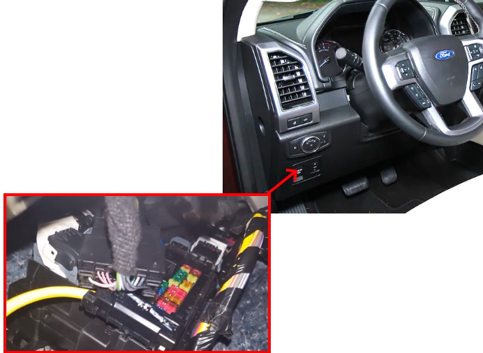
Diagram
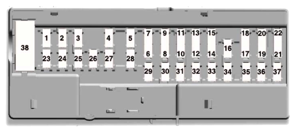
Assignment
| 1 | Not used. |
| 2 | 7,5A Driver seat switch. |
| 3 | 20A Driver door unlock. |
| 4 | 5A Trailer brake controller. |
| 5 | 20A Speaker amplifier. |
| 6 | 10A Not used (spare). |
| 7 | 10A Not used (spare). |
| 8 | Not used. |
| 9 | 10A Rear seat entertainment module. Head up display. |
| 10 | 5A Wireless AC charger module. Hands free liftgate module. Power liftgate module. Wireless charger. |
| 11 | 5A Keypad. Combined sensor module. |
| 12 | 7,5A Cluster. Electronic control panel. Smart datalink connector logic. |
| 13 | 7,5A Gear shift module. Steering column control module. |
| 14 | 10A Extended power module. Brake switch. |
| 15 | 10A Smart datalink connector power. |
| 16 | 15A Liftglass release. |
| 17 | 5A Telematics control unit – modem. |
| 18 | 5A Ignition switch. Key inhibit solenoid. Push button start switch. |
| 19 | 7,5A Transmission control switch. Gearshift module. |
| 20 | 7,5A Not used. |
| 21 | 5A Humidity and in-car temperature sensor. |
| 22 | 5A Electrochromatic mirror. Second row heated seat module. |
| 23 | 10A Moonroof logic. Inverter. Power window switch. Power mirror switch. DVD player (if equipped). |
| 24 | 20A Central lock unlock |
| 25 | 30A Left front door zone module. |
| 26 | 30A Right front door zone module. |
| 27 | 30A Moonroof. |
| 28 | 20A Stereo amplifier. |
| 29 | 30A Left rear door zone module. |
| 30 | 30A Right rear door zone module. |
| 31 | 15A Adjustable pedals. |
| 32 | 10A SYNC Drive mode switch module. 4×4 switch. Radio frequency transceiver module. Rear heating, ventilation and air conditioning control module. |
| 33 | 20A Audio control module. |
| 34 | 30A 2018: Not used. |
| 2019: Run/start relay | |
| 35 | 5A Extended power mode module. |
| 36 | 15A Image processing module A. Automated park assist module. Continuous control damping module. |
| 37 | 15A Heated steering wheel. |
| 38 | 30A Left rear power win |
Type 2
(2020 – 2024)
Location
The fuse box is in the right-hand side of the passenger footwell behind a trim panel.
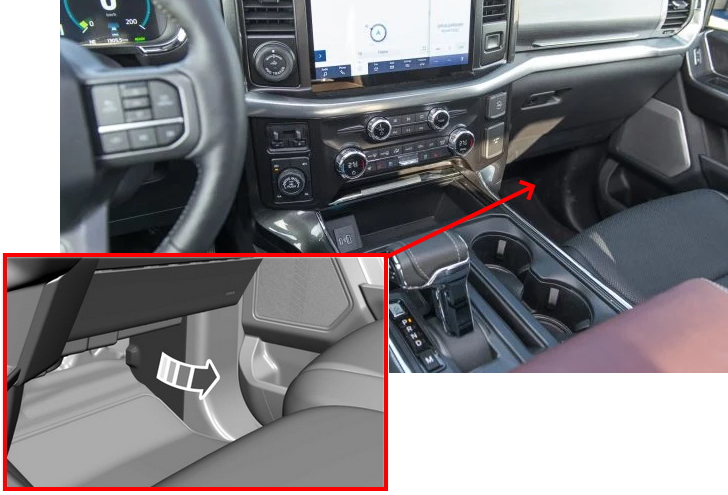
Photo example

Diagram
Designation
| 1 | Not used. |
| 2 | 10A Driver seat switch. |
| 3 | 7,5A Driver door unlock. |
| 4 | 20A Speaker amplifier. |
| 5 | Not used. |
| 6 | 10A Smart datalink connector logic. |
| 7 | 10A Rear audio control module. |
| 8 | 5A Wireless accessory charger. |
| Hands-free liftgate module. | |
| 9 | 5A Keypad. |
| Combined sensor module. | |
| 10 | Not used. |
| 11 | Not used. |
| 12 | 7,5A Instrument cluster. |
| 13 | 7,5A Steering column control module. |
| Smart datalink connector logic. | |
| Climate control module. | |
| Gearshift module. | |
| 14 | 15A Brake switch. |
| 15 | 15A SYNC. |
| 16 | Not used. |
| 17 | Not used. |
| 18 | 7,5A Gearshift module. |
| Column shifter. | |
| 19 | 5A Telematics control unit module. |
| 20 | 5A Ignition switch. |
| 21 | 5A In-vehicle temperature and humidity sensor. |
| 22 | 5A Electrochromic mirror. |
| Second row heated seat module. | |
| 23 | 30A Power window switch. |
| Power mirror switch. | |
| Left-hand front door zone module. | |
| 24 | 30A Moonroof logic. |
| 25 | 20A Speaker amplifier 2. |
| 26 | 30A Right-hand front door zone module. |
| 27 | 30A Left-hand rear door zone module. |
| 28 | 30A Right-hand rear door zone module. |
| 29 | 15A Adjustable pedals. |
| 30 | 5A Trailer tow control module. |
| 31 | 10A Rear climate control module. |
| Drive mode switch module. | |
| Terrain management switch. | |
| Radio frequency transceiver module. | |
| 4×4 switch. | |
| 32 | 20A Audio control module. |
| 33 | Not used. |
| 34 | 30A Run/start relay. |
| 35 | 5A Not used (spare). |
| 36 | 15A Image processing module A. |
| Automated park assist module. | |
| Continuous control clamping module. | |
| 37 | 20A Heated steering wheel. |
| 38 | 30A Left-hand rear power window. |
| Right-hand rear power window. |
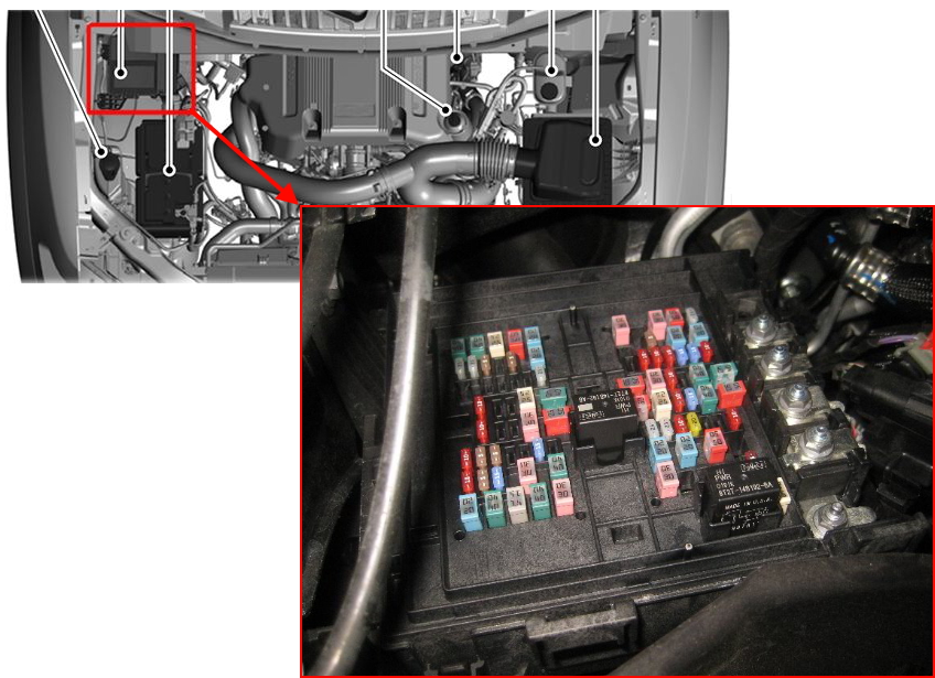
Engine compartment fuse box
Under the hood, the fuse and relay box is located on the right side of the engine compartment and is covered with a protective cover.
Type 1
Diagram

Allocation
| 1 | 25A Horn. |
| 2 | 50A Fan 1. |
| 3 | 30A Front wiper motor. |
| 4 | Not used. |
| 5 | 30A Starter relay. |
| 6 | 20A Power point 1. |
| 8 | 20A Power point 2. |
| 10 | 5A Rain sensor. |
| 12 | Not used. |
| 13 | 10A 4×4 module. Heated backlite. Heated mirror relay coil. Heated wiper park relay coil. Transmission isolation relay coil. |
| 14 | 15A Transmission control module. |
| 15 | 15A Voltage quality module right-side power. Blindspot information system. Head Up Display. Image processing module B. Front view camera. Rear view camera. Cruise control module. |
| 16 | 10A Powertrain control module (PCM) run/ start feed. |
| 17 | 10A Antilock brake system run/ start feed. |
| 18 | 10A Electronic power assist steering run / start feed. |
| 19 | Not used. |
| 20 | 40A Front blower. |
| 21 | 40A Passenger seat motors. |
| 22 | 20A Not used. |
| 23 | 10A Alternator A-line. |
| 24 | 30A Trailer brake control module. |
| 25 | 50A Body control module power 1. |
| 26 | 50A Electronic fan 3. |
| 27 | 40A Driver seat motors. |
| 28 | 15A Rear heated seats. |
| 29 | 10A Integrated wheel end solenoid. |
| 30 | 25A Trailer tow class ll-IV battery charge. |
| 31 | 50A Power folding seat module. |
| 32 | 10A A/C clutch. |
| 33 | Not used. |
| 34 | Not used. |
| 35 | 20A Vehicle power 4. |
| 36 | 10A Vehicle power 3. |
| 37 | 25A Vehicle power 2. |
| 38 | 25A Vehicle power 1. |
| 39 | Not used. |
| 41 | 50A Inverter. |
| 43 | 20A Trailer Tow Light Module Class ll-IV. |
| 45 | 20A Front/rear washer pump. |
| 46 | 7,5A Family entertainment system. |
| 47 | Not used. |
| 48 | Not used. |
| 49 | Not used. |
| 50 | 30A Fuel pump. |
| 51 | 20A Power point 3. |
| 52 | 50A Body control module (BCM) voltage quality module (VQM). |
| 53 | 25A Trailer tow park lamps relay. |
| 54 | 40A Electronic limited slip differential relay. |
| 55 | 40A AUX blower. |
| 56 | 20A Power point 4. |
| 58 | 5A Not used (spare). |
| 59 | Not used. |
| 60 | 5A Not used (spare). |
| 61 | 25A Not used (spare). |
| 62 | 25A Not used (spare). |
| 63 | 25A 4×4 module. |
| 64 | Not used. |
| 65 | Not used. |
| 66 | Not used. |
| 67 | Not used. |
| 69 | 25A 2018: Not used. |
| 2019: Trailer tow park lamp | |
| 70 | 40A Anti-lock brake system / parking brake module. |
| 71 | 25A 4×4 module. |
| 72 | Not used. |
| 73 | Not used. |
| 74 | 10A Trailer tow backup lamps. |
| 75 | Not used. |
| 76 | 50A Body control module power 2. |
| 77 | 30A Climate controlled (Heated/Vented) seat module. |
| 78 | 20A Not used (spare). |
| 79 | Not used. |
| 80 | 10A Heated wiper park. |
| 81 | Not used. |
| 82 | Not used. |
| 83 | 15A Transmission control module power. |
| 84 | Not used. |
| 85 | Not used. |
| 86 | 5A USB smart charger 5. |
| 87 | 4A USB smart charger 3. |
| 88 | 10A Multi-contour seats relay. |
| 89 | 40A Power running boards. |
| 91 | 30A Power liftgate module. |
| 93 | 15A Heated mirrors. |
| 94 | 5A USB smart charger 1. |
| 95 | 10A USB smart charger 2. |
| 96 | 30A Rear wiper motor relay. |
| 97 | 40A Intercooler puller relay fan. |
| 98 | 15A Transmission oil pump. |
| 99 | 40A Heated backlite. |
| 100 | 20A Power point 5. |
| 101 | 25A Fan 2. |
| 102 | Not used. |
| 103 | Not used. |
| 104 | Not used. |
| 105 | Not used. |
| R02 | Relay: Electronic fan 2. |
| 2019: Powertrain Control Module. | |
| R05 | Relay: Powertrain Control Module. |
| 2019: Electric fan 2 |
Cigar lighter (power outlet) fuses in this type are the fuses №6 (Power point 1), №8 (Power point 2), №51 (Power point 3), №56 (Power point 4) and №100 (Power point 5).
Type 2

Photo for example

Diagram
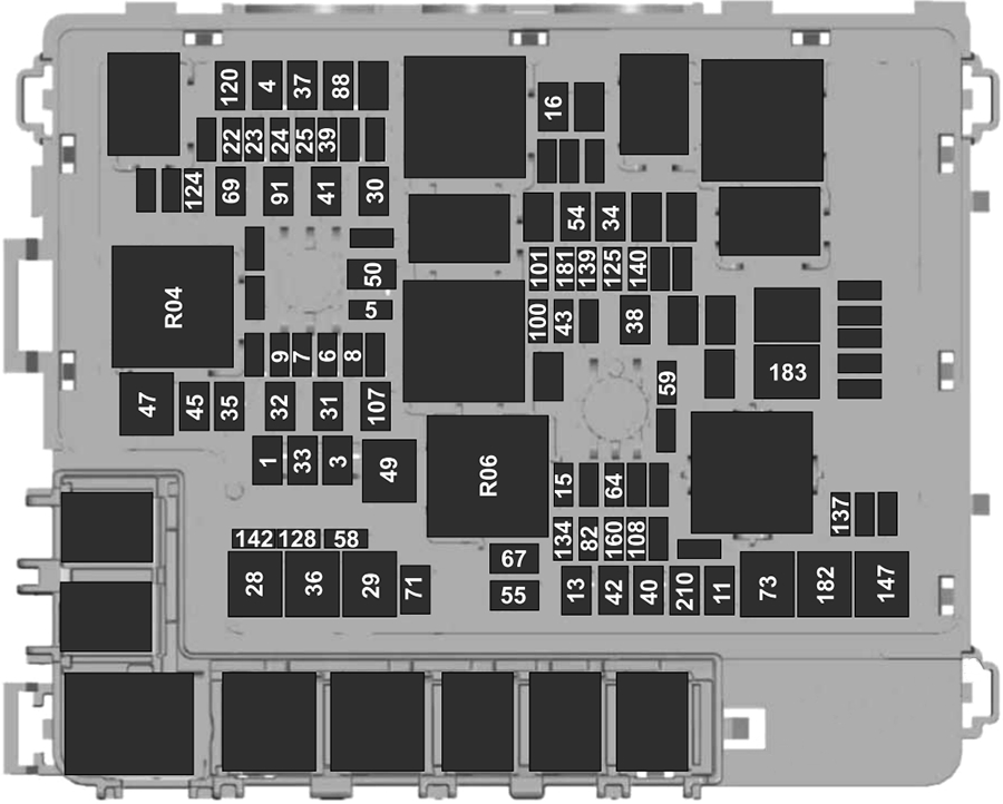
Appointment
| 1 | 30A Body control module 1. |
| 3 | 30A Body control module 2. |
| 4 | 30A Fuel pump. |
| 5 | 5A Powertrain control module relay. |
| 6 | 20A Vehicle power 1. |
| 7 | 25A Vehicle power 2. |
| 8 | 20A Vehicle power 3. |
| 9 | 20A Vehicle power 4. |
| 11 | 30A Starter relay. |
| 13 | 40A Front blower motor. |
| 15 | 20A Horn. |
| 16 | 20A Windshield washer pump. |
| 22 | 10A Electronic power assist steering run/start feed. |
| 23 | 10A Anti-lock brake system run/ start feed. |
| 24 | 10A Powertrain control module. |
| Transmission control module. | |
| 25 | 10A Rear view camera. |
| Air quality sensor run/start feed. | |
| 28 | 50A Anti-lock brake system pump. |
| 29 | 50A Anti-lock brake system valves. |
| 30 | 30A Driver seat motors. |
| 31 | 30A Passenger seat motors. |
| 32 | 20A Power point 1. |
| 33 | 20A Power point 2. |
| 34 | 20A Power point 3. |
| 35 | 20A Power point 4. |
| 36 | 40A Inverter. |
| 37 | 30A Climate controlled seats (passenger side). |
| 38 | 30A Climate controlled seats (driver side). |
| 39 | 20A Second row seat module. |
| 40 | 40A Power running boards. |
| 41 | 30A Powered liftgate module. |
| 42 | 30A Trailer brake control module. |
| 43 | 5A Not used (spare). |
| 45 | 20A Power point 5. |
| 47 | 50A Electric fan 1. |
| 49 | 50A Electric fan 2. |
| 50 | 40A Heated rear window. |
| 54 | 40A Electronic limited slip differential. |
| 55 | 30A Trailer tow parking lamps relay. |
| 58 | 10A Trailer tow backup lamps. |
| 59 | 20A Not used (spare). |
| 64 | 25A Four-wheel drive module 1. |
| 67 | 15A Transmission run/start. |
| 69 | 30A Left-hand side wiper motor. |
| 71 | 20A Rear window wiper relay. |
| 73 | 50A Power folding seat module – third row. |
| 82 | 25A Four-wheel drive module 2. |
| 88 | 40A Auxiliary blower. |
| 91 | 20A Trailer tow lighting module power. |
| 100 | 25A Left-hand headlamp. |
| 101 | 25A Right-hand headlamp. |
| 107 | 30A Trailer battery charge. |
| 108 | 20A Spot lamps (police). |
| 120 | 15A Fuel injectors. |
| 124 | 5A Rain sensor module. |
| 125 | 5A USB smart charger 1. |
| 128 | 7,5A Family entertainment system. |
| 134 | 20A Multi-contour seats relay. |
| 137 | 20A Advanced driver-assistance systems module. |
| Connected camera. | |
| 139 | 5A USB smart charger 2. |
| 140 | 5A USB smart charger 3. |
| 142 | 5A USB smart charger 5. |
| 147 | 40A Intercooler puller fan relay. |
| 160 | 10A Smart data link connector. |
| 181 | 5A Not used (spare). |
| 182 | 60A Driver door control module. |
| 183 | 60A Passenger door control module. |
| 210 | 30A Body control module start stop. |
| R04 | Electric fan 1 relay. |
| R06 | Electric fan 3 relay. |
In this type, fuses numbered 32, 33, 34, 35 and 45 are responsible for the operation of the cigarette lighters.
Check out our YouTube video for more on this topic. Don’t forget to subscribe!
If you know how to make this post better, write in the comments.