The 1st generation Ford Galaxy minivan was produced in 1995, 1996, 1997, 1998, 1999, 2000, 2001, 2002, 2003, 2004, 2005 and 2006. During this time, the car has been restyled. In our post, we will show the location of all electronic control units, which is typical for 1st generation Ford Galaxy vehicles. Let’s describe in detail the fuse boxes and relays of the Ford Galaxy Mk 1 with diagrams and photos with examples of execution. Separately, we note the fuse responsible for the cigarette lighter.

The current design of the boxes and the purpose of the elements may differ from the one presented and depends on the year of manufacture (restyling and pre-styling) and the level of electrical equipment of the car.
Contents
Location
The general arrangement of the boxes is shown in this diagram.

Designation
| 1 | Air conditioning control unit (automatic temperature control) – behind the dashboard |
| 2 | Air conditioner fan motor control unit, front (with automatic temperature control) |
| 3 | Air conditioner fan motor control unit, rear (with automatic temperature control) |
| 4 | Anti-theft control unit – in the multifunction control unit |
| 5 | Anti-theft alarm horn – intake system resonator |
| 6 | Auxiliary Battery Relay – Under Front Right Seat |
| 7 | Additional heater control unit – roof panel |
| 8 | Battery 1 |
| 9 | Battery 2 – under the front right seat (if equipped) |
| 10 | Cruise control control unit (cruise control) |
| 11 | The electric motor (drive) of the cruise control system |
| 12 | Diagnostic connector (DLC) |
| 13 | Left front power window control unit – door |
| 14 | Rear Left Power Window Control Unit – Door |
| 15 | Right front power window control unit – door |
| 16 | Rear right power window control unit – door |
| 17 | Cooling fan motor control unit |
| 18 | Fuse / relay box, instrument cluster 1 – in multifunction control box |
| 19 | Fuse / relay box dashboard 2 |
| 20 | Fuse / relay box dashboard 3 |
| 21 | Heater blower motor resistor, front (manual temperature control) |
| 22 | Heater fan motor resistor, rear (manual temperature control) |
| 23 | Sound signals – behind the bumper |
| 24 | Immobilizer control unit – behind the instrument cluster |
| 25 | Immobilizer ring antenna – near the ignition switch |
| 26 | Turn signal relay – in multifunction control unit |
| 27 | Inertia Fuel Cut Off Switch – Under Left Front Seat |
| 28 | Multi-functional control unit – in the dashboard relay fuse box 1 – functions: Rear window wiper, windshield wipers, direction indicators, hazard warning lights, power windows, interior lighting off delay function, heated windshield, heated rear window, central locking / remote control central locking control, anti-theft system, lamp health monitoring system, low / far headlights |
| 29 | Parking system control unit – luggage compartment right |
| 30 | Fog lamp relay (item 1) – left side of luggage compartment |
| 31 | Fog lamp relay (item 2) – right side of luggage compartment |
| 32 | Additional fuse 76 (15A), trailer electrical connector – under the front right seat |
| 33 | Additional fuse 77 (25A / 30A), charging system, trailer electrical connector, additional heater – under the front right seat |
| 34 | Additional fuse 78 (15A), spare – under the front right seat |
| 35 | Driver’s seat heater control unit – under the front left seat |
| 36 | Passenger Seat Heater Control Unit – Under Front Right Seat |
| 37 | Side impact sensor, driver’s side – under the front left seat |
| 38 | Passenger side impact sensor – under the front right seat |
| 39 | SRS electronic control unit |
| 40 | Trailer electrical control unit – left side of luggage compartment |
| 41 | Electronic gearbox control unit |
| 42 | Vehicle speed sensor – gearbox |
Passenger compartment
It is located under the dashboard, behind a protective cover, on the back of which there is an actual circuit with the purpose of fuses.

Main box
Type 1
Photo for example

Diagram

Appointment
| 1 | Relay for auxiliary heater |
| 2 | Relay for intermittent operation of the rear window wiper |
| 3 | Relay, electronic engine control unit |
| 4 | Relay for main ignition circuits |
| 5 | – |
| 6 | Indicator / Alarm Relay |
| 7 | Headlight washer pump relay |
| 8 | Relay for intermittent operation of the windshield wiper / washer |
| 9 | Buzzer warning about left included dimensions |
| 10 | Rear fog lamp busbar |
| 11 | Horn relay |
| 12 | Fuel pump relay (petrol) |
| 13 | Headlamp high / low beam relay |
| 14 | – |
| 15 | – |
| F1 | (7,5A) RH headlamp – low beam, headlamp corrector – LH |
| F2 | (7.5A) LH headlamp-low beam, headlamp corrector-RH |
| F3 | (3A) License plate lamps |
| F4 | (20A) Rear window wiper, heater blower motor – rear, daylight system |
| F5 | (10A) Windshield wiper motor, washer nozzle heaters |
| F6 | (25A) Heater blower motor, A / C control module |
| F7 | Front / rear dimensions – right., Warning buzzer about the dimensions left on, |
| F8 | (5A) Tail / Tailgate – Left, Headlight Leave Warning Buzzer, |
| F9 | (20A) Heated rear window |
| F10 | (15A) Light switch, fog lamps, fog lamps |
| F11 | (7.5A) High beam – LH headlamp, headlamp high beam indicator |
| F12 | (7,5A) High beam – headlamp right |
| F13 | (10A) Horns |
| F14 | (15A) Reversing lamps |
| F15 | (10A) ECM, crankcase ventilation heater |
| F16 | (3A) Clock, interior lamp – front, instrument cluster |
| F17 | (10A) Direction indicators |
| F18 | (10A) inertia fuel cut-off switch, electronic engine control module (ECM) -2.0 |
| F19 | (30A) Cooling fan motor, A / C compressor clutch relay |
| F20 | (10A) Stop lights |
| F21 | (10 / 15A) Interior lamps, clock, tail lamp, cigarette lighter |
| F22 | (10A) Diagnostic system, air conditioning system, cigarette lighter |
| F23 | (10A) Cooling fan motor, A / C compressor clutch relay |
| F24 | (30A) Windshield wiper motor |
| F25 | (60A) Glow plugs |
| F26 | (10A) Oxygen sensor |
| F27 | (50A) Heated windscreen relay |
| F28 | (30A) Traction control / anti-lock brake control system |
| F29 | (30A) Traction control / anti-lock brake control system |
| F30 | (10A) Central locking, door marker lamps |
| F31 | (10A) Anti-theft alarm horn |
| F32 | (10A) Hazard alarm (anti-theft system) |
| F33 | – |
| F34 | (25A) Cooling fan motor relay |
| F35 | (20A) Trailer socket |
| F36 | – |
| F37 | (30A) Power glass lifters |
| F38 | (20A) Power seat |
| F39 | (25A) Cooling fan motor relay |
The fuses F21 and F22 are responsible for the operation of the cigarette lighter.
Type 2
the photo

Diagram

Assignment
| F1 | (20A) Heated seats |
| F2 | (10A) Instrument panel, instrument cluster lights, power lift glass, power door mirrors |
| F3 | (5A) ABS system, interior lamps, instrument cluster illumination, cigarette lighter , clock, cruise control, heating / ventilation system, auxiliary heater, air conditioning system, navigation system, sunroof |
| F4 | (10A) Engine management system, anti-theft system |
| F5 | (15A) Parking system, reversing light (s), automatic transmission control system, 4WD system, navigation system, trailer electrical connector |
| F6 | (10A) Horn |
| F7 | (20A / 25A) Cigarette lighter, clock |
| F8 | (30A) Charging system, windscreen wiper / washer, auxiliary heater, trailer electrical connector |
| F9 | (30A) Anti lock brake system (ABS) |
| F10 | (30A) Anti lock brake system (ABS) |
| F11 | (20A) Headlamp washers |
| F12 | (15A) Cigarette lighter, clock, windshield wiper / washer, sunroof |
| F13 | (3A) Engine management |
| F14 | (10A / 20A / 25A) Engine management system, cruise control system, heating / ventilation system, air conditioning system |
| F15 | (30A) Engine management system, air conditioning system |
| F16 | (10A / 30A) Engine management system, air conditioning system |
| F17 | (10A / 30A) Engine management system, automatic transmission control system, heating / ventilation system |
| F18 | (5A) Engine management system, air conditioning system |
| F19 | (5A) Diagnostic socket, anti-theft system, instrument cluster, air conditioning, audio system, audio CD changer, telephone, navigation system, central locking, power lift glass |
| F20 | (10A) ABS system, automatic transmission control system, engine management system, brake lights, instrument cluster, cruise control system, navigation system, trailer electrical connector |
| F21 | (25A30A) Air conditioner auxiliary heater |
| F22 | (25A30A) Air conditioner auxiliary heater |
| F23 | (10A) Audio system, audio system CD changer, navigation system |
| F24 | (25A) Heating / ventilation system |
| F25 | (3A) Instrument cluster, audio system, audio CD changer, navigation system, telephone |
| F26 | (30A) Automatic transmission control system, starter relay – immobilizer, engine management system, instrument cluster |
| F27 | (25A) Engine management, windshield heater, air conditioning / heating system auxiliary heater |
| F28 | (10A) ABS system, air conditioning system, engine management system, windshield wiper / washer, headlight washers |
| F29 | (5A) Windshield wiper / washer, heated rear window, heating / ventilation system, air conditioning system, auxiliary heater |
| F30 | (3A) Tail lamps, license plate lamps, trailer electrical connector |
| F31 | (15A) Fog lights, trailer electrical connector |
| F32 | (3A / 10A) Engine management system, cruise control system, air conditioning system |
| F33 | (25A / 30A) Charging system, windshield wiper / washer, auxiliary heater, trailer electrical connector |
| F34 | (25A) Heating / ventilation system, air conditioning system, auxiliary heater |
| F51 | (20A) Heated rear window |
| F52 | (20A) Direction indicators, hazard warning lights trailer electrical connector, anti-theft system |
| F53 | (10A) Door opening lamps, interior lamps |
| F54 | (10A) Anti-theft system |
| F55 | (5A) Door opening lamps, instrument cluster, anti-theft system, central locking, electric lift glass |
| F56 | (5A) RH side / tail lights, trailer electrical connector, daytime lighting, instrument cluster |
| F57 | (5A) LH side / tail lights, trailer electrical connector, daytime running light, instrument cluster |
| F58 | (10A) Headlamp adjustment, daytime running light system, LH headlamp, RH headlamp |
| F59 | (10A) LH headlamp – low beam, instrument cluster, LH headlight range control, daytime running light system |
| F60 | (10A) RH headlamp – low beam, instrument cluster, right headlight range control, daytime running light |
| F61 | (10A) LH headlamp-high beam, instrument cluster |
| F62 | (10A) RH headlamp-high beam |
In this version, fuse number 7, 20A, is responsible for the operation of the cigarette lighter.
Relay box
Located on the back of the main unit.

Type 1
Diagram
Designation
| 1 | Folding mirror control unit |
| 10a | Horn relay |
| 10b | Relay for auxiliary heater |
| 11a | Relay glass of the lift of the rear side window, left. |
| 11b | Relay glass of the lift of the rear side window, right |
| 12a | Fully Open Throttle Position Relay – Automatic |
| 12b | Fully open throttle position relay |
| 13a | Heater fan motor relay – front. |
| 13b | Cooling fan motor relay |
| 17a | Heater fan cut-off relay 1 |
| 17b | Heater fan shutdown relay 2 |
| 18a | Heater fan shutdown relay 3 |
| 18b | – |
| 2 | Folding mirror control unit |
| 3 | Fuel boost pump relay -Diesel |
| 4 | Relay of the electric motor of the fan of the cooling system – 2.0 / 2.3 |
| 5 | Air Conditioning Compressor Electromagnetic Clutch Control Unit – Diesel |
| 6 | Transmission control relay |
| 7 | Steering wheel control unit |
| 8 | Steering wheel control unit |
| 9 | Daytime Lighting Relay – If Equipped |
| 14 | – |
| 15 | – |
| 16 | Relay 2 rear side window lift glass |
| 19 | Headlight washer pump relay |
Type 2
Diagram

Assignment
| 20 | Fuel pump relay – 2.8 Cooling fan motor relay |
| 21 | Engine control system relay – 2.0 / 2.3 |
| 22 | Exhaust Air Pump Relay – 2.8 |
| 23 | Windshield heater relay |
| 24 | Fuel pump relay – 2.0 / 2.3 |
| 25 | Brake light relay |
| 26 | Relay for auxiliary ignition circuits |
| 27 | Relay for main ignition circuits |
| F70 | (30A) Exhaust air system – petrol |
| F73 | (50A) Heated windscreen |
| F74 | (50A) Exhaust air system – Diesel |
| F75 | (30A) Power glass lifters |
Type 3
Diagram

Designation
| 18 | Relay for auxiliary heater |
| 19 | Daytime running light relay |
| 20 | Overrunning clutch lock relay |
| 21 | Rear ventilation window relay |
| 22 | Heated windshield relay |
| 23 | 4×4 servotronic relay |
| 24 | Power window relay |
| 25 | Break relay |
| 26 | Warning unit (timer) |
Engine compartment
It is located on the left side of the engine compartment and also includes high power fuse links.

Main fuse box
Diagram

Appointment
| F100 | (3A) Fuse / relay box, instrument cluster 1 (F55) |
| F101 | (30A) Anti lock brake system (ABS) |
| F102 | (30A) Anti lock brake system (ABS) |
| F103 | (60A) Auxiliary heater, glow plugs |
| F104 | (40A) Cooling fan motor 1 |
| F105 | (40A) Cooling fan motor relay |
| F106 | (110A) Fuse / relay box 1, instrument panel (F13 / F25 / F27), fuse / relay box 3, instrument panel (F75) |
| F107 | (150A) Generator |
Additional box
On some models, another unit is installed under the hood.
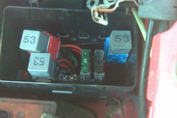
Diagram

Protected components
| 57 | 30A Air pump | |
| 58 | 40A Cooling fan | |
| 59 | 30 / 40A Cooling fan | |
| Relay | ||
| 50 | Fan relay (3rd speed) | |
| 51 | Throttle valve relay | |
| 52 | Fan relay (2nd speed) | |
| 53 | Deceleration relay | |
| 54 | Fan relay (1st speed) or Coolant pump diode | |
| 55 | Automatic transmission relay | |
| 56 | Air pump relay | |
We have posted a video on our YouTube channel. Watch and subscribe.
Did not find an answer to your question? write in the comments.
Hi thanks for your illustrations for galaxy 1.9 1999
Type 2 fuse box drivers side as per picture, i have no fuses blown
But No auxiliary relay unit left hand side in engine compartment so where find relay switches ??
Shorted battery and lost brake lights, indicators, int lights, radio and central locking but other electrics working.
Kindvregards