Volkswagen Tiguan is a compact crossover produced in 2 generations from 2007 to the present. The 1st generation Volkswagen Tiguan was produced in 2008, 2009, 2010, 2011, 2012, 2013, 2014, 2015 and 2016. During this period, he was restyled once. In this article you will find a designation of the fuse and relay boxes in the Volkswagen Tiguan with their photos – examples and diagrams. Separately, we highlight the fuse responsible for the cigarette lighter.

Contents
Locations
Diagram

Assignment
- Main fuse box in the communication box
- Switching fuse box.
- Passenger compartment fuse box.
- Relay box.
The actual purpose of the fuse box depends on the year of manufacture and the vehicle equipment level.
Passenger compartment
Fuse box
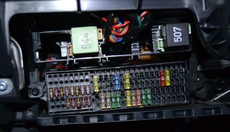
It is located in the passenger compartment, in the lower part of the parting panel on the driver’s side, behind the protective cover.

Photo for example
Diagram
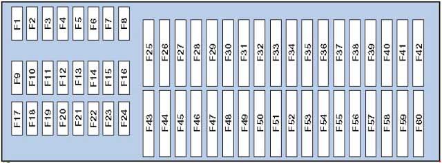
Designation
| 1 | Not used |
| 2 | Not used |
| 3 | Not used |
| 4 | Not used |
| 5 | Not used |
| 6 | Not used |
| 7 | Not used |
| 8 | Not used |
| 9 | 5A Airbag control unit, control lamp off. front passenger airbags |
| 10 | 10A All-wheel drive control unit |
| 11 | 5A The control unit for the parking autopilot or assistant |
| 12 | 10A Left headlight discharge lamp control unit |
| 13 | 5A High pressure sensor, Electrochromic interior rearview mirror, Reversing light switch, Washer jet heating resistor, AUTO HOLD button, AUTO HOLD indicator lamp, Seat occupied recognition control unit, Front camera for driver assistance systems, Engine oil level and temperature sensor , ASR and ESP off key, Drive program key |
| 14 | 10A Power steering control unit, Vehicle position tracking control unit, Starter relay, Electronic damping control unit, Trailer detection control unit, Tiptronic switch, Data bus diagnostic interface, Control unit in instrument cluster, Heater control unit, Light switch , Engine control unit, ABS control unit |
| 15 | 10A Relay for auxiliary heater operation, Voltage converter, Control unit for adaptive lighting and headlight range control, Air mass meter, Diagnostic connector, Control unit for electromechanical parking brake, Dimmer for switches and instrument cluster illumination, Heating resistor for crankcase ventilation system, Control motor headlamp corrector, right headlight corrector actuator |
| 16 | 10A Right headlight discharge lamp control unit |
| 17 | 5A Instrument cluster control unit |
| 18 | 5A Control unit for mobile phone control electronics, Multimedia system control unit, Magnetic field sensor for compass |
| 19 | 7.5A Steering column control unit |
| 20 | 5 / 7.5A Tire pressure monitor control unit, Radio signal receiver for auxiliary coolant heater, Heated rear window relay, Two-tone horn relay, ABS control unit, Tiptronic switch, Automatic transmission control unit, Air conditioning control unit, Climatronic control unit , Heater control unit |
| 21 | 7.5 / 15A Onboard supply control unit, front passenger door control unit, rear right door control unit |
| 22 | 5A Onboard supply control unit, Alarm siren, Interior sensor |
| 23 | 10A Rain and light sensor, Light switch, Vehicle position tracking control unit, Entry and start authorization control unit, Rear view camera control unit, Magnetic field sensor for compass, Electromechanical parking brake button, Diagnostic connector |
| 24 | 10A Driver’s door control unit, Rear left door control unit |
| 25 | 5 / 20A Multifunction switch, Automatic transmission control unit, DSG mechatronic unit |
| 26 | Not used |
| 27 | Not used |
| 28 | 40A Relay for auxiliary heater operation, Heater control unit, Air conditioning control unit |
| 29 | 15A Rear window wiper motor |
| 30 | Not used |
| 31 | 20A Cigarette Lighter & 12V Socket |
| 32 | Not used |
| 33 | Not used |
| 34 | Not used |
| 35 | Not used |
| 36 | Not used |
| 37 | Not used |
| 38 | 10A Electronic steering column lock control unit |
| 39 | 20A Relay for headlight cleaning system |
| 39 | 15A Trailer recognition control unit / preparation for towing hitch |
| 40 | 15A Trailer recognition control unit |
| 41 | 15A Trailer recognition control unit |
| 42 | 20A Trailer recognition control unit |
| 43 | 25A Sliding sunroof control unit |
| 44 | 25A Electromechanical parking brake control unit |
| 45 | 25A Supply fan relay, Heated rear window relay |
| 46 | 30A Driver’s door control unit, Rear left door control unit |
| 47 | 30A Front passenger door control unit, Rear right door control unit |
| 48 | 20A Fuel pump relay |
| 49 | 20A Onboard supply control unit |
| 50 | 25A Electromechanical parking brake control unit |
| 51 | 40A Supply fan control unit |
| 52 | 20 / 30A Front seat heating control unit |
| 53 | 20 / 30A Relay for headlight cleaning system |
| 54 | 30A Inverter with socket, 12V – 230V |
| 55 | 15A Switch for adjusting the lumbar support of the driver’s seat |
| 56 | 15A Electronic damping control system control unit |
| 57 | 25A sunroof control unit |
| 58 | 1A Traction hitch warning lamp (locked) |
| 59 | Control unit with display for radio navigation system |
| 60 | Not used |
The fuse number 31 at 20A is responsible for the cigarette lighter in the 1st generation Volkswagen Tiguan
Relay box
The relay box is located on the back of the fuse box.

Diagram
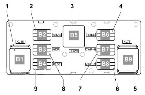
Relay assignment
- Power relay terminal 15 2, -J681-, (460) Slot B1
- Heated exterior mirror relay -J99- (449) Slot B2
- Heated rear window relay -J9- (53) Slot B5
- Dual tone horn relay -J4- (449) Slot B6
- X contact relief relay -J59- (460) Slot B9
- Double washer pump relay 2 -J730- (404) Slot B8
- Relay 1 for double washer pump -J729- (404) Slot B7
- Reserve Slot B3
- Power relay 2 terminal 30 -J689- (449) Slot B4
Diagram
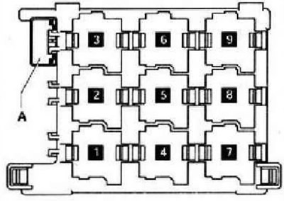
Designation
- Auxiliary heater relay
- Starter relay
- –
- Heater fan relay
- Burglar Alarm Relay / Headlight Washer Pump Relay
- Fuel pump relay (FP)
- Engine coolant heater relay 1
- Engine Coolant Pump Relay – Some Models, Fuel Pump (FP) Relay – Some Models, Auxiliary Heater Fuel Pump Relay – Some Models
- Engine coolant heater relay 2
Engine compartment
It consists of a section of fuses and relays (Main section – 1) and high power fuses (main fuses – 2) and is located next to the battery, under a protective cover.
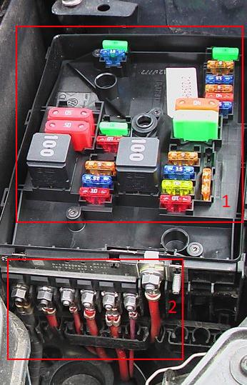
Main fuse department
Type 1
Fuse box diagram

Designation
| 1 | |
| 2 | |
| 3 | 5A Onboard supply control unit |
| 4 | 30A ABS control unit, ABS hydraulic unit |
| 5 | |
| 6 | 5A Instrument Cluster Control Unit, Steering Column Control Unit |
| 7 | 40A Relay 2 power supply terminal 15 |
| 8 | 25A Control unit with display for radio navigation system, Head unit, TV tuner, Digital satellite radio tuner, Control unit for multimedia system, Voltage converter |
| 9 | 5A Mobile phone control electronics control unit |
| 10 | 5 / 10A Power relay, Engine control unit |
| 11 | 20A Additional heater control unit |
| 12 | 5A Data bus diagnostic interface |
| 13 | 15 / 30A Engine control unit |
| 14 | 5A Fuel pressure regulator, Fuel metering valve, Ignition coils |
| 15 | 5/10 / 15A Solenoid clutch for drive blower, Lambda probe heater, Lambda probe 1 heater after catalytic converter, Fuel system diagnostic pump, Fuel pump relay, Glow plug control unit, Electric fuel pump relay 2 |
| 16 | 30A Onboard supply control unit |
| 17 | 15A Alarm siren relay |
| 18 | 30A Amplifier for digital audio system |
| 19 | 30A wiper motor control unit |
| 20 | 10A Fuel pressure regulator, coolant circulation pump |
| 21 | 10 / 20A Lambda probe heater, Fuel pump control unit |
| 22 | 5A Clutch pedal position sensor |
| 23 | 10A Solenoid valve for boost pressure limitation, Exhaust gas recirculation cooler changeover valve, Fuel pressure regulator, Air mass meter |
| 24 | 10A Radiator fan control unit, Heating relay, Relay for additional cooling system pump, Power relay, Solenoid valve for boost pressure limitation, Solenoid valve 1 of the adsorber, Valve 1 for variable valve timing, Charge air recirculation valve, Intake manifold flap valve, Circulation pump 2 coolant, coolant circulation pump, fuel pump relay |
| 25 | 40A ABS control unit |
| 26 | 30A Onboard supply control unit |
| 27 | Not used |
| 28 | 50A Glow plug control unit |
| 29 | 50A Thermal fuse 1 for adjusting the position of the driver’s seat, Fuses 54 – 57 in the passenger compartment |
| 30 | 50A Relay for unloading contact X |
- A1 – Relay of the main ignition circuits (diesel)
- A2 – Engine control relay (EC) (diesel)
Type 2
the photo
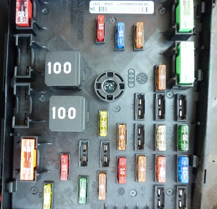 Appointment
| 1 | 15A Block Mechatronik KP DSG |
| 2 | 30A ABS control unit |
| 3 | 15A Horn relay |
| 4 | Reserve |
| 5 | 5A Onboard supply control unit |
| 6 | Reserve |
| 7 | 25A Voltage converter, Control unit with display for radio navigation system, Control unit for multimedia system |
| 8 | 40A Relay 2 power supply terminal 15 |
| 9 | Reserve |
| 10 | 5 / 10A Lambda probe heating element, Electromagnetic clutch of the drive blower, Diagnostic pump of the fuel system, Glow plug control unit |
| 11 | 5A Instrument Cluster Control Unit, Steering Column Control Unit |
| 12 | 5A Mobile phone control electronics control unit |
| 13 | 5 / 10A Engine control unit |
| 14 | 15 / 30A Engine control unit |
| 15 | 5A Data bus diagnostic interface |
| 16 | 10A Boost Pressure Limiting Solenoid Valve, Recirculation Radiator Switching Valve, Air Flow Meter, Fuel Pressure Regulator |
| 17 | 10 / 15A Fuel pressure regulating valve, coolant circulation pump |
| 18 | 10A Lambda probe heater 20A Fuel pump control unit |
| 19 | 30A Amplifier for digital audio system |
| 20 | 5A Clutch pedal position sensor |
| 21 | 30A Additional heater control unit |
| 22 | 30A wiper motor control unit |
| 23 | 10A High heating power relay, Low heating power relay, Fuel pump relay, Coolant circulation pump 2, Radiator fan control unit, Electric fuel pump relay 2, Boost pressure limiting solenoid valve, Charge air recirculation valve, Canister solenoid valve 1, Valve 1 variable valve timing systems, Intake manifold flap valve, Motronic power relay 2, Brake light switch |
| 24 | 20A Ignition coils 15A Fuel metering valve |
| 25 | 30A Onboard supply control unit |
| 26 | 30A Onboard supply control unit |
| 27 | 50A Relay for unloading contact X |
| 28 | 50A Glow plug control unit |
| 29 | 50A Thermo fuse 1 for adjusting the position of the driver’s seat, Fuses 54 – 57 in the passenger compartment |
| 30 | 40A ABS control unit (Pump) |
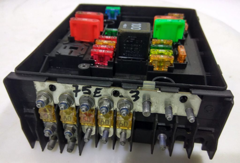
Main fuses
Diagram
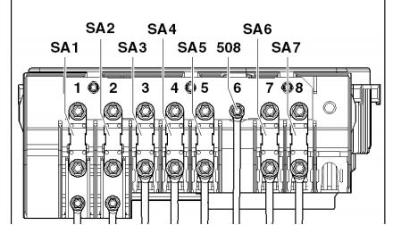
Assignment
- 200A – Generator
- 80A – Power steering control unit
- 50A – Fuse 40 in the fuse box
- 50A – Radiator fan control unit
- 80A – Fuse box
- 70A – Radiator fan control unit, High power heating relay
- Reserve
- 40A – Low power heating relay
We have posted a video on our YouTube channel. Watch and subscribe.
If you know how to make the material better, write in the comments.
my Tiguan 2009 model tsi 2.0 litre, fuel gauge is not indicating, its showing empty. the A/C is blowing air but it is not cooling and the car is indicating negative temperature while it is hot during the day. somehow someone touched the fuses. what must i do
I have 2011 Tiguan SE and have front left low beam not working.
replacing bulb did not work. No juice to the bulb. I tried to find the fuse.
Some says #12, another says 30A fuse in the fuse box under the hood.
All the diagram and pictures above are a little different from my car. My goal is to find the fuse for Left Low beam headlamp. Anyone can help on this?
My vw tiguan is misfiring but I’ve changed spark plugs and coils. Even the pick up is reduced. What could be the problem?
The message above has helped me so much
Kelebogile keekae
Is there any codes out there?
Did you ever find the fuse?
EPC fault coming while engine start and vibrating the engine.It’s not happening always . Could you pls help me to diagnostic
VW Tiguan R -Line 2016 gcc model
Zdravim mam Tig 2009 tdi foremotion 4×4 mel sem upalen jeden z vodicu na hlavni skrini a nemuzu si vzpomenout zapojeni, Nema nekdo z vas foto ci pdf jak je to zapojeny? diky
Thank you