Volkswagen Passat B7 – represents the 7th generation of the passat series. But at the same time, this is not a completely new model, in many ways it represents a deep restyling of the previous generation b6 . Even their interior is very similar. Produced in 2010, 2011, 2012, 2013, 2014 and 2015. In our article you will find a designation of fuses and relays Volkswagen Passat B7 with photographs and box diagrams in which they are located. Let’s highlight the fuse responsible for the cigarette lighter. We will also show the location of all electronic control units.

The purpose of fuses and relays, as well as their number, may differ from the one presented and depends on the configuration of your car and its year of manufacture.
Contents
Layout

Designation
| 1 | ABS electronic control unit |
| 2 | Air conditioner electronic control unit |
| 3 | Auxiliary Heater Control Unit – Front Right Fender Interior |
| 4 | Battery (some models) |
| 5 | Battery (some models) – Left side of luggage compartment |
| 6 | Diagnostic connector (DLC) |
| 7 | Diagnostic unit |
| 8 | Driver’s door control unit |
| 9 | Rear left door electrical control unit |
| 10 | Passenger door electrical control unit |
| 11 | Rear right door electrical control unit |
| 12 | Electronic engine control unit (ECM) – on the resonator of the intake system |
| 13 | Electronic control unit 4WD – on the Haidex coupling |
| 14 | Fuel pump control unit – under the rear right seat |
| 15 | Fuse / relay box, engine compartment 1 |
| 16 | Fuse / relay box, engine compartment 2 |
| 17 | Fuse / relay box, engine compartment 3- under engine fuse / relay box 1 |
| 18 | Fuse / relay box, instrument cluster 1 |
| 19 | Fuse / relay box, instrument panel 2 |
| 20 | Fuse / relay box, instrument panel Z |
| 21 | Fuse / relay box, instrument cluster 4 |
| 22 | Fuse / relay box, instrument panel 5 |
| 23 | Fuse / Relay Box, Luggage Compartment 1 – 3.6 FSI |
| 24 | Fuse / Relay Box, Luggage Compartment 2- Stop & Start System |
| 25 | Headlight range control unit |
| 26 | Heater fan motor resistor – in the heater block |
| 27 | Beep 1 |
| 28 | Beep 2 |
| 29 | Lane Departure Control Module 1 – Rear Bumper |
| 30 | Lane Departure Control Unit 2 – Rear Bumper |
| 31 | Multifunction control unit ^ Functions: Electric load control. Exterior lamps, footwell lamps, fuel pump, heated rear window, defrosted windscreen, turn signals / hazard warning lights, rear window wiper |
| 32 | Multifunctional control unit 2- functions: Anti-theft system, central locking. drive for opening the fuel filler flap, immobilizer, Central locking remote control system, sunroof |
| 33 | Ambient temperature sensor |
| 35 | Parking brake control unit |
| 36 | Power steering control unit – on the steering rack |
| 37 | Seat heating control unit – under the driver’s seat |
| 38 | Steering column electronics control unit – on the steering column |
| 39 | Steering column lock control unit – on the steering column |
| 40 | Stop-start system control unit |
| 41 | SRS electronic control unit |
| 42 | Suspension control unit – luggage compartment right |
| 43 | Trailer control unit – left luggage compartment |
| 44 | Electronic Transmission Control Unit (TCM) (DSG Transmission) |
| 45 | Electronic Transmission Control Unit (TCM) (Automatic Transmission) – Inner Fender (Front Left) |
Location of fuse and relay boxes
Diagram

Appointment
- Passenger side instrument panel fuse box
- Box next to the battery
- Box behind trim in luggage compartment
- Driver’s side instrument panel fuse box
- Relay boxes
- Fuse and relay box under the hood
- Main fuse box
Passenger compartment
Driver side fuse box
It is located in the left end of the instrument panel, behind the protective cover.
Photo for example

Diagram
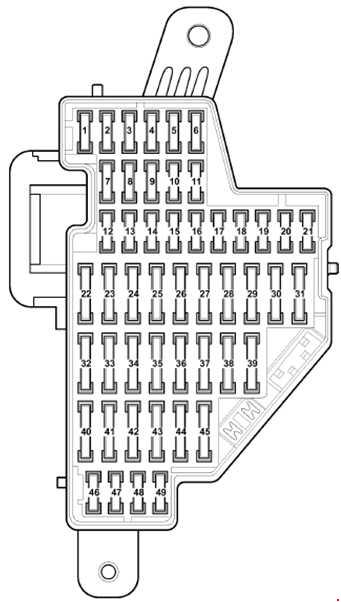
Assignment
| 1 | 10A Rear window blinds, High pressure sensor, Air pollution sensor, Oil level and temperature sensor, Supply fan relay |
| 2 | 5A ASR and ESP off button, AUTO HOLD button, ABS unit, Electromechanical parking brake control unit |
| 3 | 10A Power supply relay, Crankcase ventilation heating resistor, Gas valve |
| 4 | 10A Electronic damping control control unit, Diagnostic connector, Start-stop button, Adaptive cruise control control unit, Parking aid control unit, Trailer detection control unit, Park assist control unit, Front camera for driver assistance systems |
| 5 | 10A Dimmer for switches and instrument cluster illumination, Headlight range control, Left headlight control unit |
| 6 | 10A All-wheel drive control unit |
| 7 | 5A Instrument Cluster Control Unit, Data Bus Diagnostic Interface |
| 8 | 10A Right headlight control unit, right headlight range control actuator |
| 9 | 10A Airbag control unit, Seat occupied recognition control unit, Front passenger airbag deactivation warning lamp |
| 10 | 10A Tiptronic switch, Air mass meter, Fuel pump control unit, Fuel pump control unit, Motronic power relay, Engine control unit, Starter relay |
| 11 | 5A Emergency data logger key, Mirror with taximeter, Tachograph |
| 12 | 10A Driver’s door control unit, Front passenger door control unit, Comfort unit |
| 13 | 10A Light switch, diagnostic connector, selector, ABS control unit |
| 14 | 10A Alarm Siren |
| 15 | 10A Rain and light sensor, Heated rear window relay, Heated windscreen relay, Climatronic control unit, Air conditioning control unit, Rear view camera control unit, Terminal and engine start control unit |
| 16 | 10A Electronic ignition lock, Electronic steering column lock control unit, Terminal enable and engine start control unit |
| 17 | 15A Driver’s door control unit, Driver’s side rear door control unit |
| 18 | 3A Onboard supply control unit, Voltage stabilizer, Engine control unit, Power supply relay 2 |
| 19 | 7.5A Adaptive cruise control control unit, Park assist control unit, Lane departure warning control unit, Park assist control unit |
| 20 | 5A Garage door opener control panel |
| 21 | 10A Rear curtain control unit |
| 22 | 20A Electromechanical parking brake control unit |
| 23 | 15A Trailer recognition control unit |
| 24 | 20A Electromechanical parking brake control unit |
| 25 | 20A Trailer recognition control unit |
| 26 | 20A Onboard supply control unit |
| 27 | 15 / 20A Fuel pump relay |
| 28 | 30A Rear door control unit, Convenience system central control unit |
| 29 | 20A Rear seat heating control unit |
| 30 | 20A Sliding sunroof control unit |
| 31 | 30A Inverter with socket, 12V – 230V |
| 32 | 30A Onboard supply control unit (heated rear window) |
| 33 | 30A Relay for headlight cleaning system, headlight washer pump |
| 34 | 25A Front seat heating control unit |
| 35 | 15A Tailgate control unit, Driver seat lumbar adjustment switch |
| 36 | 15A Switch for adjusting the lumbar support of the seat, Button for adjusting the angle of inclination of the seat cushion, Button for adjusting the position of the backrest, Trailer power relay |
| 37 | 20 / 30A Trailer detector control unit, Luggage compartment lid control unit 2 |
| 38 | 40A Supply fan relay, Supply fan control unit, Climatronic |
| 39 | 5 / 15A Multifunction switch (only for vehicles with 6-speed automatic transmission), Automatic transmission control unit, Reversing light switch, DSG gearbox mechatronic unit |
| 40 | 20A Second battery charging relay, Windscreen washer pump, Rear window wiper motor |
| 41 | 20A Cigarette lighter |
| 42 | 15A Socket 12V |
| 43 | 20A Additional heater control unit (only with a second battery) |
| 44 | 30A Driver and passenger door control unit |
| 45 | 20А Relay for operation in the autonomous heater mode (only in the presence of a second battery) |
| 46 | Not used |
| 47 | 10A Telephone transceiver (only vehicles with start-stop system) |
| 48 | 5A Control unit in the instrument cluster (only vehicles with start-stop system) |
| 49 | Not used |
The fuse number 41, 20A, is responsible for the cigarette lighter. And for the headlight washers – 33 to 30A.
Passenger side fuse box
Located in the right end of the dashboard, just like the left, it is covered with a protective cover.
Diagram
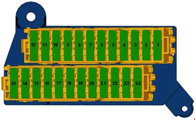
Assignment
| 1 | 15 / 30A Tailgate control unit, Trailer detection control unit |
| 2 | 15 / 30A Tailgate control unit 2, Trailer detection control unit |
| 3 | 10 / 30A Sunroof blind control unit, Trailer detection control unit |
| 4 | 15A BU for electronic damping control system |
| 5 | Not used |
| 6 | Not used |
| 7 | Not used |
| 8 | Not used |
| 9 | Not used |
| 10 | Not used |
| 11 | Not used |
| 12 | Not used |
| 13 | Special vehicles |
| 14 | Special vehicles |
| 15 | Special vehicles |
| 16 | Portable radio or flashlight charger |
| 17 | Special vehicles |
| 18 | Special vehicles |
| 19 | Special vehicles |
| 20 | Special vehicles |
| 21 | Special vehicles |
| 22 | Special vehicles |
| 23 | Special vehicles |
| 24 | Special vehicles |
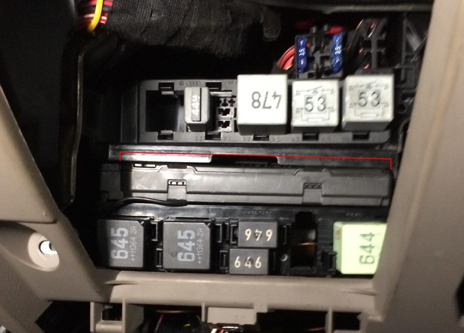
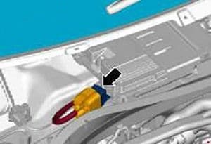
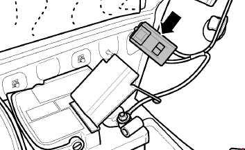
Relay boxes
They are located under the dashboard, on the driver’s side, behind the trim.
Photo for example
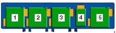
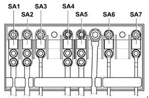
Upper relay box
Diagram

Designation
| 1 | Supply fan relay (Climatic with auxiliary heater) |
| 2 | Relay for auxiliary heater operation (Climatic with auxiliary heater) |
| 3 | Relay for auxiliary heater operation (Diesel engine with auxiliary heater) |
| 4 | Not used |
| 5 | Coolant circulation relay after off Engine (1.8L / 2.0L TFSI only), Power Relay |
| 6 | Relay for power supply terminal 50 (not for vehicles with start-stop system) |
| 7 | Power supply relay 2 (not for vehicles with start-stop system) |
| 8 | Power supply relay 2 (not for vehicles with start-stop system) |
A and B – Thermal fuse for adjusting the position of the driver’s seat
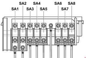
Lower relay box
Diagram
Designation
| 1 | Heated rear window relay (645) |
| 2 | Terminal 15 power supply relay (645) |
| 3 | Dual tone horn relay (646), Headlamp cleaning relay (646) |
| 4 | Trailer power relay (from May 2012) |
| 5 | Relay for unloading contact X (644) |
Please note that other relay elements can also be located separately, for example, the Relay for charging the second battery.
Engine compartment
The fuse and relay box is located on the left side of the engine compartment under the protective cover and consists of 2 sections: a mounting box and a section for high power main fuses. Not far from it is the relay communication unit.
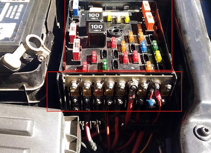
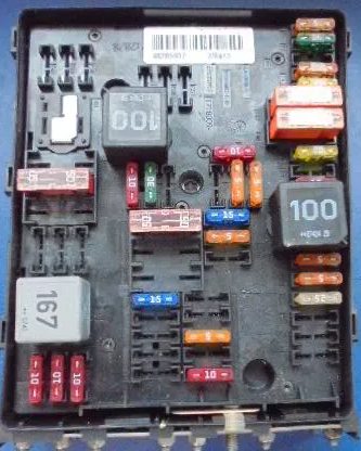
Mounting box
Type 1

Diagram
 Appointment
| 1 | 15A Block Mechatronik KP DSG |
| 2 | 30A ABS control unit |
| 3 | 20A Horn, Onboard supply control unit |
| 4 | 20A Trailer recognition control unit |
| 5 | 5A Control unit for battery monitoring, Onboard supply control unit |
| 6 | 5A Automatic gearbox control unit, 15A DSG gearbox mechatronic unit |
| 7 | 15A Control unit with display for TV and radio navigation system, Head unit, Control unit with display for radio navigation system, 30A Voltage stabilizer |
| 8 | 30A DSG gearbox mechatronic unit |
| 9 | 5A Steering column control unit |
| 10 | 20A Fuel pump relay (diesel only), Glow plug control unit, Ignition coils with output stage (cylinders 1 – 4) |
| 11 | 5A Control unit in the instrument cluster (only vehicles with start-stop system) |
| 12 | 5A Control unit for control electronics of a mobile phone, Antenna, TV tuner, Digital satellite. |
| 13 | 10A Power relay Motronic, Power relay cl. 30, Engine control unit |
| 14 | 25 / 30A Engine control unit |
| 15 | 5 / 10A Data bus diagnostic interface |
| 16 | 15A Relay for pumping coolant after off. engine, 10A Exhaust gas recirculation valve, Solenoid valve for boost pressure limitation, Lambda probe heating element |
| 17 | 40A Low power heating relay, Coolant circulation pump, Shut-off and safety valve for 1 gas cylinder |
| 18 | 10/15 / 30A Fuel quality sensor, High pressure valve for gas operation |
| 19 | 30A Amplifier |
| 20 | 5A Additional fuel pump relay, Radiator fan control unit, Glow plug control unit, 10A Clutch pedal position sensor, Variable valve timing valve 1, 15A Fuel pressure regulator |
| 21 | 20A Additional heater control unit |
| 22 | 30A wiper motor control unit |
| 23 | 5A Magnetic field sensor for compass, Glow plug control unit, 10A Electronically controlled engine cooling thermostat, Radiator fan control unit, Air / intake flap motor, Heating element lambda probe, valve timing and manifold |
| 24 | 10 / 15A Nitrogen oxide emission sensor control unit, Lambda probe heater |
| 25 | 40A Onboard supply control unit, Dipped beam, High beam, Dimensions |
| 26 | 40A Onboard supply control unit, Dipped beam, High beam, Dimensions |
| 27 | 60A Heated windshield element |
| 28 | 40 / 50A Secondary air pump motor, Glow plug control unit |
| 29 | 50A Control unit for onboard fuse supply, Contact relief relay X |
| 30 | 50A Onboard fuse network control unit |
Type 2
Diagram
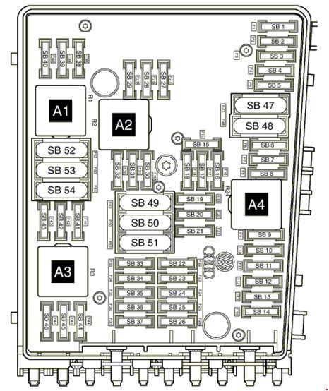
Designation
| 1 | 5 / 15A Automatic gearbox control unit, DSG mechatronic unit |
| 2 | 30A ABS control unit |
| 3 | 20A Convenience system central control unit, Trailer recognition control unit |
| 4 | 5A Onboard supply control unit |
| 5 | 20A Sound signal |
| 6 | 20A Ignition coils with output stages |
| 7 | 15A Fuel pressure regulator, 5A Clutch pedal position sensor |
| 8 | 10A Radiator fan control unit, Timing valve, Ejection pump valve, Intake manifold flap valve |
| 9 | 5A Circulation pump relay |
| 10 | 10A Power relay 2 Motronic, lambda probe heating element |
| 11 | 25 / 30A Engine control unit |
| 12 | Not used |
| 13 | Not used |
| 14 | Not used |
| 15 | 10A Circulation pump |
| 16 | 5A Steering column control unit |
| 17 | 5A Instrument cluster control unit |
| 18 | 30A Amplifier, Control unit for special vehicles |
| 19 | 15 / 20А Head unit, Control unit with display of radio navigation system |
| 20 | 20A Mobile phone, TV, digital satellite |
| 21 | 10A TV Tuner, Digital Satellite Radio Tuner |
| 22 | 7.5A Multimedia system control unit |
| 23 | 10A Radiator fan control unit, 5A Magnetic field sensor for compass |
| 24 | 5 / 10A Data bus diagnostic interface |
| 25 | Not used |
| 26 | 10A Engine Control Unit, Motronic Power Relay |
| 27 | Not used |
| 28 | Not used |
| 29 | Not used |
| 30 | 20A Additional heater control unit |
| 31 | 30A wiper motor control unit |
| 32 | 10A Boost pressure valve |
| 33 | 15A Fuel pressure regulator, Lambda probe heating element |
| 34 | Not used |
| 35 | 20A Relay for auxiliary heater operation |
| 36 | Not used |
| 37 | Not used |
| 38 | Not used |
| 39 | Not used |
| 40 | Not used |
| 41 | Not used |
| 42 | Not used |
| 43 | Not used |
| 44 | 10A Diagnostic pump of the fuel system |
| 45 | 10A Lambda Sensor |
| 46 | 10A Heating element for lambda probe 1 after catalyst |
| 47 | 40A Onboard supply control unit, dipped headlights, side lights |
| 48 | 40A Onboard supply control unit, dipped headlights, side lights |
| 49 | Onboard fuse supply control unit |
| 50 | Not used |
| 51 | 60A Relay of high power heating |
| 52 | 60A Heated windshield element |
| 53 | 50A Onboard supply control unit, Left fuse box |
| 54 | 50А Э / motor for additional air supply, Glow plug relay |
Relay
- A1 – Relay for gas shut-off valves
- A2 – Relay for pumping coolant after off. engine
- A3 – Reserve
- A4 – Main relay
Main fuse box
It consists of high power fuses in the form of fusible links.
Type 1
Diagram
Assignment
| 1 | 150 / 180A – Generator |
| 2 | 80A Electric motor for electric power steering |
| 3 | 50 / 80A Radiator fan control unit |
| 4 | 80 / 100A Thermal fuse 1 seat adjustment, Fuse box left / right |
| 5 | 80A Right Fuse Box (up to April 2008), Driver’s Seat Adjustment Thermal Fuse 1 |
| 6 | 80 / 100A Fuse box left / right |
| 7 | 40A ABS control unit |
Type 2
Diagram
Designation
| 1 | 150A – Generator |
| 2 | 80A Electric motor for electric power steering |
| 3 | 50 / 80A Radiator fan control unit |
| 4 | 60A Thermal Fuse 1 Seat Adjustment, Left / Right Fuse Box |
| 5 | 60 / 80A Thermal fuse 1 seat adjustment, Fuse box left / right |
| 6 | 80 / 100A Fuse box left / right |
| 7 | 60А Second battery charging cable, 100А – heating element of additional air heater, Relay of high heating power |
| 8 | 40A ABS control unit |
Relay box
Diagram

Protected components
| 1 | Starter relay 1 (643) – only for vehicles with start-stop system |
| 2 | Glow plug control unit (457) |
| 3 | Not used |
| 4 | Low power relay (53) |
| 5 | High power heating relay (100) |
| 6 | Starter relay 2 (489) – only for vehicles with start-stop system |
A separate heated windscreen relay can be located in the plenum chamber next to the engine control unit.
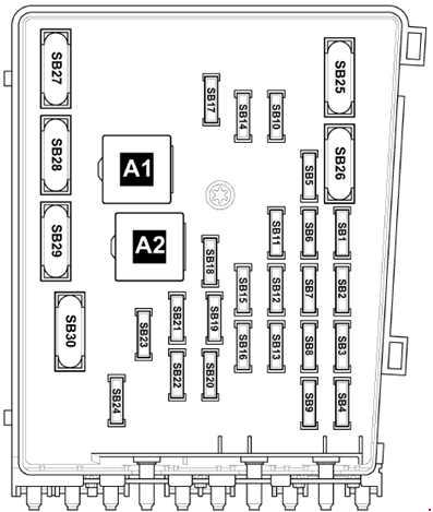
Luggage compartment
Some models with a battery installed in the luggage compartment have additional protection elements in the form of fuses and relays.

Appointment
| 1 | 30A Fuse box left / right |
| 2 | 80A Fuses in the switching unit |
| 3 | 125A Power supply of the switching unit |
| 4 | 5A Onboard supply control unit |
In the left part of the luggage compartment behind the side lining, several relay elements can be located: 70A – Limousine, 60A – Variant
We have posted a video on our YouTube channel. Watch and subscribe.
That’s all. We hope that this material was useful to you. And if you have something to add, write in the comments.
where is the relay for a 2012 vw passat a/c
I have a 2013 Volkswagen Passat S. From all the pictures and diagrams not one matches the fuse box under the hood. I’m trying to figure out where the horn relay is. I don’t have the relays in the lower section on the driver’s side. What’s there is a little storage compartment like a little glove box. As I said earlier nothing you have matches where I’m assuming is the fuse and relay box. There are some things that look like maybe relays but can’t find anything that matches my car
Hello and thanks for the site. I have a problem with an electronic towbar on a Passat 2013 that wont go in and suspect that it could be the fuse. Do you know wich fuse that could be?
Fredrik
Radiator fan relay location on 2014 passat tdi se.
Zdravo i hvala na sajtu. Imam problem sa elektronskom kukom za vuču na Passatu iz 2013. koja neće da se uključi i sumnjam da bi mogao biti osigurač. Znate li koji bi to osigurač mogao biti?