The Volkswagen Sharan has been on the market from 1995 to the present in two generations. 1st generation was produced in 1996, 1997, 1998, 1999, 2000, 2001, 2002, 2003, 2004, 2005, 2006, 2007, 2008 and 2009. During this time, the car was restyled 2 times. Accordingly, there are also several box execution diagrams. In this material, we will show the location of all electronic control units, we will describe in detail the purpose of fuses and relays in the 1st generation Volkswagen Sharan. Separately, we note the cigarette lighter fuse.

The number of units, their design and the purpose of the elements may differ from the one presented and depend on the year of manufacture, the level of equipment and the country of delivery. We will present 2 of the most popular options: the 1st option is suitable mainly for models produced before 1998, and the 2nd after.
Contents
Locations
Diagram

Designation
| 1 | Air conditioner electronic control unit |
| 2 | Heater air conditioner fan motor control unit, front (with automatic temperature control) |
| 3 | Heater air conditioner fan motor control unit, rear (with automatic temperature control) |
| 4 | Antenna signal amplifier – behind the roof panel |
| 5 | Anti-theft control unit Central locking control unit – under the driver’s seat (^ 08/97) |
| 6 | Anti-theft control unit – in the multifunction control unit (09/97 ^) |
| 7 | Anti-theft alarm horn – intake system resonator (^ 04/00) |
| 8 | Anti-theft alarm horn – intake system resonator (05/00 ^) |
| 9 | Audio aerial – rear right side window |
| 10 | Additional battery – under the passenger seat, if equipped |
| 11 | Additional battery relay (11/98 ^) – under the front right seat |
| 12 | Additional heater control unit |
| 13 | Accumulator battery |
| 14 | Central locking control unit – in the anti-theft system control unit – under the driver’s seat (^ 08/97) |
| 15 | Central locking control unit – in the multifunction control unit (09/97 ^) |
| 16 | Control Unit (Alarm) – Instrument Panel Fuse / Relay Box 2 |
| 17 | Cruise control control unit (cruise control) |
| 18 | Diagnostic connector (DLC) – ^ 04/00 – under the front ashtray |
| 19 | Diagnostic connector (DLC) – 05/00 ^ |
| 20 | Left front power window control unit -door |
| 21 | Rear Left Power Window Control Unit – Door |
| 22 | Right front power window control unit – door |
| 23 | Rear right power window control unit – door |
| 24 | Cooling fan motor control unit |
| 25 | Electronic control unit 4WD – on the clutch |
| 26 | Fuse / relay box, instrument cluster 1 – in multifunction control unit (09/97 ^) |
| 27 | Fuse / relay box dashboard 2 |
| 28 | Fuse / relay box dashboard 3 |
| 29 | Fuse / relay box, engine compartment 1 |
| 30 | Fuse / relay box, engine compartment 2 |
| 31 | Heater blower motor resistor, front (manual temperature control) |
| 32 | Heater fan motor resistor, rear (manual temperature control) |
| 33 | Sound signals – behind the bumper |
| 34 | Immobilizer control unit – behind the instrument cluster |
| 35 | Immobilizer ring antenna – near the ignition switch |
| 36 | Turn signal relay – in multifunction control unit |
| 37 | Multifunction control unit – in dashboard fuse / relay box 1 – functions: windshield defroster / rear defroster, windshield wipers / rear window wiper, direction indicators, hazard warning lights, interior lamps, power windows, central locking, central remote control lock, anti-theft system |
| 38 | Antenna for navigation system, telephone |
| 39 | Parking aid control unit – under the driver’s seat |
| 40 | Parking system buzzer, front – under the driver’s seat |
| 41 | Parking system buzzer, rear – under the tail lamp cover |
| 42 | Additional fuse (30A / 40A), additional battery – under the front right seat |
| 43 | Additional fuse (30A), additional heater (09/01 ^) – under the front right seat |
| 44 | Additional fuse (15A), accessory power connector 1 ^ 1/98 – 05/00) – under the front right seat |
| 45 | Additional fuse (15A), accessory power socket 2 ^ 1/98 – 05/00) – under the front right seat |
| 46 | Seat heating control unit, driver’s side – under the driver’s seat |
| 47 | Seat heating control unit, passenger side – under the passenger seat |
| 48 | Side impact sensor, on the driver’s side – under the driver’s seat |
| 49 | Side impact sensor, passenger side – under the passenger seat |
| 50 | SRS electronic control unit |
| 51 | Body height sensor, front – headlight range control on anti-roll bar |
| 52 | Body height sensor, rear – headlight range control – rear right axle shaft |
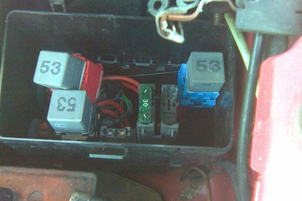
| 53 | Electronic gearbox control unit – engine compartment, left |
| 54 | Vehicle speed sensor – at checkpoint |
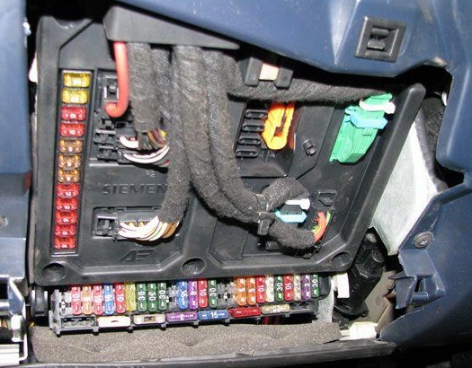
Passenger compartment
The main fuse and relay boxes are located on the left side of the dashboard, behind the protective cover.

There will be an additional relay box behind it.
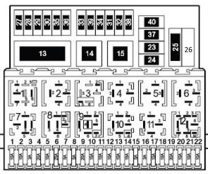
Fuse box
Type 1

Diagram
Assignment
| 1 | – |
| 2 | (72) Rear window washer wiper relay |
| 3 | (30/109) Engine management relay – ADY / AKT / 1Z / AHU / AFN |
| 4 | (18) Ignition auxiliary circuits relay |
| 5 | – |
| 6 | (21/22) Alarm relay |
| 7 | (95) Headlight washer pump relay |
| 8 | (19/99) Relay for intermittent operation of the windshield washer wiper |
| 9 | (36) Headlamps warning buzzer |
| 10 | (53) Fog lamp relay |
| 11 | (53) Horn relay |
| 12 | (167) Fuel pump relay – AAA / ADY / AKT |
| 13 | (128) Traffic light switching relay |
| 14 | (169) Heated rear window relay |
| 15 | (53/204) Windshield wiper motor relay |
| F1 | (10A) LH headlamp – low beam, headlamp range-left |
| F2 | (10A) RH headlamp – low beam, headlamp adjustment – RH |
| F3 | (3A) License plate lamps |
| F4 | (20A) Wiper, rear window washer, daylight system, air conditioning / heater blower motor – rear |
| F5 | (10A) Windshield washer wiper, windshield washer nozzle heaters |
| F6 | (25A) A / C system, A / C / heater blower motor |
| F7 | (5A) RH side / tail lamp, engine compartment lamp |
| F8 | (5A) LH / LH lamps |
| F9 | (20A) Heated rear window, defroster relay |
| F10 | (15A) Rear fog lamps |
| F11 | (10A) LH headlamp |
| F12 | (10A) RH headlamp |
| F13 | (10A) Horn |
| F14 | (15A) Reversing light (s), cruise control, heated windshield relay, central locking, power windows, power door mirrors, seat heater, air conditioning, auxiliary heater, 4WD system, automatic transmission (automatic transmission) , automatic transmission selector backlight |
| F15 | (5A / 10A) Engine management system, immobilizer, gearbox selector backlight, crankcase breather heater, exhaust gas recirculation system (EGR) valve, fuel vapor accumulator valve |
| F16 | (3A) Clock, interior lamp – front, glove compartment lamp, rear window defogger relay, instrument cluster |
| F17 | (10A) Direction indicators |
| F18 | (10A) Fuel pump, heated oxygen sensor – AAA / ADY / AKT |
| F19 | (30A) Cooling fan motor control module, coolant blower motor |
| F20 | (10A) Brake light switch (brake pedal position sensor) |
| F21 | (10A) Instrument cluster, clock, audio system, audio CD changer, audio output amplifier, interior lamps, sunroof |
| F22 | (10A) Air conditioning, diagnostic connector (DLC) |
| F23 | (7.5A) Cooling fan motor control unit, coolant pump motor, A / C compressor magnetic clutch |
| F24 | (30A) Windshield wiper |
| F25 | (60A) Glow plugs |
| F26 | Reserve |
| F27 | (50A) Heated windscreen |
| F28 | (30A) ABS control module |
| F29 | (30A) ABS control module |
| F30 | (10A) Central locking |
| F31 | (10A) Central locking, anti-theft alarm horn |
| F32 | (10A) Central locking, warning lamps – anti-theft system |
| F33 | (25A / 30A) Additional heater |
| F34 | (25A) Air conditioning / heater blower motor – rear |
| F35 | (20A) Cigar lighter, trailer electrical connector, bodywork power connectors |
| F36 | (10A) Telephone |
| F37 | (30A) Power windows |
| F38 | (20A) Spare |
| F39 | (25A) Front Climatronic module |
| F40 | (5A) Cooling fan motor relay 1 and 2 speed |
In this version, the fuse number 35 for 20A is responsible for the cigarette lighter, 22 for additional sockets.
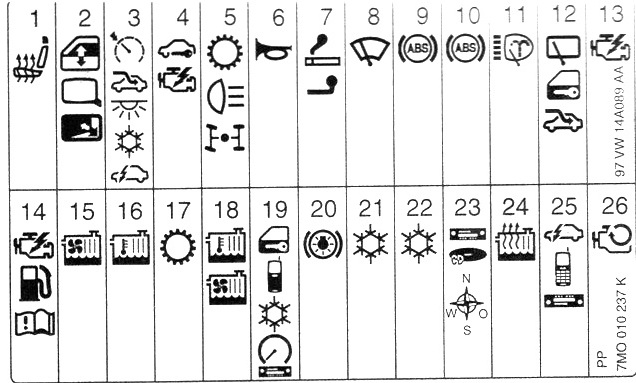
Type 2
The current appointment can be presented in the form of a brochure located on the back of the protective cover.
Diagram

Designation
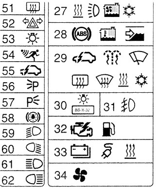
Protected components
| 1 | (20A) Heated seats |
| 2 | (10A) Power windows, power door mirrors |
| 3 | (5) Cruise control, sunroof, glove box illumination, clock, navigation system, air conditioning system, auxiliary heater, multifunctional unit / board |
| 4 | (10A) Engine management, immobilizer, crankcase breather heater-AAA / AMY / ANU |
| 5 | (15A) Reversing light (s), automatic transmission (AT), AWD system |
| 6 | (10A / 25A) Buzzer |
| 7 | (20A) Cigarette lighter |
| 8 | (30A) Windshield wiper / washer |
| 9 | (30A) Anti-lock braking system (ABS) |
| 10 | (30A) Anti-lock braking system (ABS) |
| 11 | (20A) Headlamp washers |
| 12 | (15A) Sunroof, clock, multifunction control module: Central locking, rear window wiper / washer |
| 13 | (3A) Engine management – petrol |
| 14 | (10A / 20A / 25A / 30A) motor control |
| 15 | (30A) Cooling fan motor -AAA / AFN / AHU |
| 16 | (15A / 30A) Cooling fan motor (06/00 ^) |
| 17 | (10A) Automatic transmission |
| 18 | (5A / 10A) Cooling fan motor |
| 19 | (5A) Central locking, telephone, air conditioning, instrument cluster, audio system, parking system (11 / 98-05 / 00), diagnostic connector (DLC) |
| 20 | (10A) Stop lights |
| 21 | (25A / 30A) air conditioner |
| 22 | (25A / 30A) air conditioner |
| 23 | (10A) Audio system, audio system CD changer, navigation system |
| 24 | (25A) Auxiliary heater |
| 25 | (3A) Multifunction control module, telephone, audio system |
| 26 | (30A) Start inhibit switch relay / reversing lamp relay |
| 27 | (25A) A / C system, coolant blower motor |
| 28 | (10A) Anti-lock braking system (ABS), coolant blower motor, windshield wiper / washer |
| 29 | (5A) Multifunction control module, windshield washer nozzle heaters, windshield wiper (- ^ 10/98), heated windscreen, heated rear window, auxiliary heater, heating ventilation (-10/98), air conditioning |
| 30 | (3A) License plate lamps |
| 31 | (15A) Fog lights |
| 32 | (3A / 10A) Engine management-ADY / AAAAJ H / AKT / ANU |
| 33 | (25A) Trailer electrical connector, bodywork power connector (12v), additional battery |
| 34 | (25A) Heating / ventilation system |
| 51 | (20A) Heated rear window |
| 52 | (20A) Direction indicators |
| 53 | (10A) Interior lamps |
| 54 | (10A) Anti-theft system |
| 55 | (5A) Door opening lamps, instrument cluster, anti-theft system, central locking, power windows |
| 56 | (5A) Front right side marker, rear right side marker lamps |
| 57 | (5A) LH, Tail lamps |
| 58 | (10A) Headlight range control |
| 59 | (10A / 15A) LH headlamp – low beam |
| 60 | (10A / 15A) RH headlamp – low beam |
| 61 | (10A) LH headlamp-high beam |
| 62 | (10A) RH headlamp-high beam |
In this embodiment, the fuse number 7, 20A, is responsible for the cigarette lighter, 8 for additional sockets.
Relay boxes
Type 1
Main box
Diagram

Functions of the elements
- 1 Splitter Diagnostics
- 2 Splitter Terminal 15a
- 3 Splitter Terminal 58b
- 4 Speed signal splitter
- 5 Splitter Terminal 54
- 6 End splitter off doors
- 18 – Radio loudspeaker switching relay – telephone
- 19 – Daytime Lighting Relay (200)
- Reserve
- 31 – Relay for rear ventilation windows (149)
- 22 – the Relay for heating a windshield (170)
- 23 – Not used
- 24 – Relay for electric glass lifters (53)
- 25 – Rear heater supply fan relay (94)
- 26 – Warning relay not wearing seat belts
Type 2
Main box
Diagram

Designation
| 1 | (361) Control unit for folding mirrors |
| 2 | (361) Control unit for folding mirrors |
| 3 | Audio / Telephone Speaker Switch Relay |
| 4 | (94) Heater blower motor relay – without air conditioning |
| 5 | (53/131/181) Cooling fan motor cut-off relay (after stopping the engine) |
| 6 | (175) Start inhibit switch relay / reversing lamp relay |
| 7 | (106) Auxiliary heater relay (^ 04/98) |
| 8 | (95) Headlight washer pump relay |
| 9 | (200) Daytime Lighting Relay – If Equipped |
| 10 | (53/404) Horn relay |
| 11 | (94) A / C compressor electromagnetic clutch relay – AFN / AHU |
| 12 | (168) A / C compressor electromagnetic clutch relay |
| 13 | (153) Diode |
| 14 | (185) Immobilizer relay |
| 15 | (114) Heater blower motor relay – auxiliary heater (^ 04/98) |
| 16 | (149) Relay for power rear side windows |
| 17 | (53/404) Auxiliary heater relay |
| 18 | (94) Coolant pump relay |
| 19 | (109) Engine management relay |
Additional box

Diagram

Functions of elements
- 50A – Heated windshield
- 50A – Secondary air pump, 25A – Additional heater
- 25A – Additional heater
- 30A – Separate fuse for glass – lifters
| 20 | (404) Auxiliary heater operation relay |
| 21 | (53) Windshield wiper motor relay / radiator fan relay (361) |
| 22 | (53) Exhaust air pump relay / heated exterior mirrors relay (404) |
| 23 | (100) Heated windscreen relay |
| 24 | (167) Fuel pump / blower relay (53) |
| 25 | (53) Coolant heater relay |
| 26 | (100) Ignition auxiliary circuits relay |
| 27 | (114) A / C compressor magnetic clutch cut-off relay |
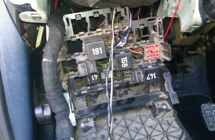
Engine compartment
The main power fuse box is located next to the battery and is covered by a cover.
Main box
the photo

Assignment
- 60A – Glow plugs
- 40A – Radiator fan
- 40 / 60A – Radiator rotator
- 110A – Salon interior
- 150A – Generator
- 3A – Multifunctional control unit
- 30A – ABS
- 30A – ABS (pump)
On some models, another additional unit was installed
Additional box
Diagram
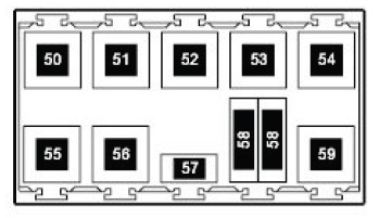
Designation
- 50 – Air conditioning decoupling relay (114)
- 51 – Relay off air conditioner (147)
- 52 – Reserve
- 53 – Reserve
- 54 – Relay of high power heating (103)
- 55 – Relay for starter and reversing lights (158)
- 56 – Air pump relay (53)
- 57 – Secondary air pump relay
- 58 – Fuse for radiator fan, glow plugs of additional heating elements for coolant
- 59 – Relay low heating power (103)
We have posted a video on our YouTube channel. Watch and subscribe.
That’s all. And if you have any questions, ask them in the comments.
Do you have the 2012 VW Sharan diagrams?
i have sharan goal 2005 and i got diferent fuse boxs
Excellent information and useful. Thanks for the valuable information.
I have a 2016 seat Alhambra which is really a VW sharan. Do you have a diagram for this model?
Good day, I have sharon 2003 model. Whenever I am driving the door light and inner light blink. What can cause it
There could be a few potential causes for this issue. Here are some possibilities to consider:
1) The blinking lights may indicate a problem with one of the door switches. These switches are responsible for detecting whether a door is open or closed. If a switch is faulty or becomes loose, it may send incorrect signals to the light circuit, causing the lights to blink.
2) Another possibility is that there is a loose electrical connection somewhere in the lighting system. Vibrations from driving can cause loose connections to intermittently disconnect and reconnect, leading to blinking lights.
3) It’s also possible that there is a problem with the wiring in the door or interior light circuit. Worn-out or damaged wiring can cause intermittent connections, resulting in blinking lights.
4) And last one is malfunction in the vehicle’s electrical system could be the culprit. This could be due to a faulty relay, control module, or other electrical component that controls the lights. A diagnostic scan using specialized equipment may be necessary to identify the specific cause.
Dear sirs,
My front lights do not work.
I need central electronics part, namely fuse box type2 for Sharan 1,9TDI diesel, 81kW, year 1999.
If you know how to solve this problem, please inform me as soon as possible.
Best regards,
Edin
Vw Sharon 2008 no power on trip wire (yellow) when ignition is turned on getting no fuel ……..get fuel when the wire for fuel is jumped! Where does yellow wire go? Ignition ,ecm? Thanks..