Toyota Sienna 2 nd generation was produced in 2003, 2004, 2005, 2006, 2007, 2008, 2009, 2010 with the designation XL20. During this time, the model received a facelift. In this publication we will present information with the location of electronic control units, description of fuses and relays Toyota Sienna 2 with fuse box diagrams and photo examples of their performance. Let’s note the cigarette lighter fuse.

The location of the units and the purpose of the elements in them may differ from the one shown and depends on the year of manufacture, the level of electrical equipment and the region of delivery of your vehicle.
Contents
Passenger compartment
Location
ECM Location

General layout

Assignment
- Wiper zone heater relay
- Fuse box
- Body electrical control unit
- Interior lighting relay
- Turn signal relay (emergency signaling)
- Inverter relay
- Parking Sensor Control Unit (Clearance Sonar)
- Air conditioner control unit
- Key transponder computer
- Central lock receiver
- Antenna amplifier
- Audio amplifier
- Distance control system control unit
- Additional fuse box
- Engine control unit
- Transmission selector lock unit
- Airbag unit
- Key transponder amplifier
Fuse box
In the vehicle interior, the main fuse and relay box is located in the lower part of the instrument panel behind the protective cover.

The block itself will look something like this.

Diagram

Designation
| 1 | 10A MIR HTR – Heated mirrors |
| 2 | 7.5A RAD2 – Audio, navigation, rear passenger entertainment system |
| 3 | 15A PWR OUTLET – Power outlet |
| 4 | 15A CIG – Cigarette Lighter |
| 5 | 7.5A ECU ACC – Transmission selector lock, air conditioning, power mirrors |
| 6 | 7.5A GAUGE2 – Instrument cluster |
| 7 | 7.5A IGN – Multipoint fuel injection system/sequential multipoint fuel injection system, SRS airbag system, body electrical control unit |
| 8 | 15A INJ – 2003-2006: Multipoint fuel injection system/sequential multipoint fuel injection system |
| 7.5A IG2 – 2007-2010: Multipoint fuel injection system/sequential multipoint fuel injection system | |
| 9 | 15A RR WIP – Rear windshield wiper |
| 10 | 30A WIP – Front Wiper, Rear Wiper |
| 11 | 10A GAUGE1 – Back-up lamps, turn signal lamps, emergency warning lamp |
| 12 | 15A S-HTR – Heated seats |
| 13 | 20A WSH – Front window washer, rear window washer |
| 14 | 10A HTR – Air conditioning |
| 15 | – |
| 16 | 10A ECU-IG – Parking assist, rearview monitor, body electrical control unit, multi-point fuel injection system/sequential multi-point fuel injection system, ABS, VSC, TRC, transmission selector lock, dynamic cruise control, heated seats, power tailgate, sunroof, multi-information display, interior rearview mirror, power windows, power outlet (115 V), third row of seats, memory of driver’s settings |
| 17 | 10A PANEL – Air conditioning, heated seats, audio system, navigation, sliding doors, power tailgate, trip display, heated rear window, emergency alarm, instrument panel illumination, ignition switch illumination |
| 18 | 10A TAIL – Clearance light, license plate light |
| 19 | 25A S/ROOF – Sunroof. |
| 20 | – |
| 21 | 15A AC INV – Socket (115 V) |
| 22 | 15A FR DEF – Heated wiper zone |
| 23 | 7.5A AM1 – Multi-point fuel injection system / sequential multi-point fuel injection system, starting system |
| 24 | – |
| 25 | – |
| 26 | 10A STOP – Stop lamps, auxiliary stop lamp, transmission selector lock, ABS, VSC, TRC, multipoint fuel injection system/sequential multipoint fuel injection system, body electrical control unit |
| 27 | 25A P/W – Power windows, power mirrors |
| 28 | 7.5A OBD – Diagnostic connector |
| 29 | 15A FOG – Front fog light |
| 30 | – |
| 31 | – |
| 32 | 15A PA/ENT – Rear A-pillars |
15A fuses 3 and 4 are responsible for the operation of the cigarette lighters.
Some fuses and relays may be attached to the other side of the unit.
Diagram
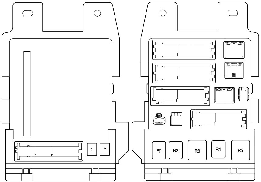
Designation
| 1 | 30A P / SEAT – Power Seats |
| 2 | 30A POWER – Electric windows |
| Relay | |
| R1 | Fog lights |
| R2 | Rear lights, parking lights |
| R3 | Auxiliary relay (ACC) |
| R4 | Power relay (PWR) |
| R5 | Ignition (IG1) |
Additional fuse box
Installed in the instrument panel behind the glove compartment.

Purpose
- 50 7.5A ST – Multi-point fuel injection system/sequential multi-point fuel injection system
- 51 7.5A A/C – Mechanical air conditioning
- 52 5A SFT – Transmission selector lock
Additional elements
Layout

Decoding
- Left mirror control unit
- Right mirror control unit
- Sunroof control unit
- Right sliding door control unit
- Rear wiper relay
- Trunk door control unit
- Left sliding door control unit
Engine compartment
Location
Engine compartment

Allocation
- Stability control unit
- Fuse and relay box
- Left headlight control unit
- Cooling fan control unit
- Right headlight control unit
Fuse box and relays
Photo example of location

Check the fuse and relay assignments against your diagrams on the back of the protective cover.

Diagram

Appointment
| 1 | 30A MAIN – Headlights, daytime running lights, fuses: “H-LP RL”, “H-LP LL” |
| 2 | 30A AM2 – Fuses: “INJ”, “IGN”, “GAUGE2” |
| 3 | 10A ETCS – Multipoint fuel injection system/sequential multipoint fuel injection system |
| 4 | 20A DRL – Daytime running lights, fuses: “H-LP RH”, “H-LP LH” |
| 5 | 25A DOOR NO.2 – Central locking system |
| 6 | 10A HORN – Horn |
| 7 | 10A DOME – Interior lighting, personal lighting, sun visor mirror lighting, door lighting, luggage compartment lighting, multi-information display, engine compartment lighting |
| 8 | 20A RAD NO.1 – 2003-2006: Audio system, navigation. |
| 15A RAD NO.1 – 2007-2010: Audio system | |
| 9 | 20A EFI NO.1 – Multi-point fuel injection system / sequential multi-point fuel injection system, fuse: “EFI NO.2” |
| 10 | 7.5A ALT-S – Charging system |
| 11 | 15A HAZ – Turn indicators, emergency signaling |
| 12 | 10A ECU-B – Sliding doors, air conditioning, power windows, instrument cluster, body electrical control unit, wireless remote control system |
| 13 | 15A H-LP RL – Near Right Light |
| 15A H-LP RH – Far right light | |
| 14 | 15A H-LP LL – Middle left light, fog light |
| 15A H-LP LH – Far left light | |
| 15 | 30A RAD NO.3 – Audio system |
| 16 | 10A EFI NO.2 – Multi-point fuel injection system / sequential multi-point fuel injection system |
| 17 | 25A A/F – Air/Fuel Ratio Sensor |
| 18 | 15A SPARE – Spare fuses |
| 19 | 20A SPARE – Spare fuses |
| 20 | 30A SPARE – Spare fuses |
| 21 | 30A SPARE – Spare fuses |
| 22 | 50A RR2 SEAT – Third row of seats |
| 23 | 50A HTR – Air conditioning, fuse: “A/C” |
| 24 | 50A FAN – Cooling fan |
| 25 | 30A PBD – Electric tailgate actuator |
| 26 | 30A R-PSD – Right sliding door |
| 27 | 30A L-PSD – Left sliding door |
| 28 | 40A RR A/C – Rear Air Conditioner |
| 29 | 40A DEF – Rear window heater, fuse: “MIR HTR” |
| 30 | 7.5A SPARE – Spare fuse |
| 31 | 140A ALT – Charging system, fuses: “RR A/C”, “HTR”, “FAN”, “PBD”, “R-PSD”, “L-PSD”, “DEF” |
| 32 | 50A ABS1 – ABS, VSC, TRC |
| 33 | 30A ABS2 – ABS, VSC, TRC |
| 34 | 30A ST – Starting system |
| 35 | 30A L-RR2 SEAT – Third row of seats |
| 36 | 30A R-RR2 SEAT – Third row of seats |
| 37 | 10A H-LP RH – Far right light |
| 10A H-LP RL – Middle left light | |
| 38 | 10A H-LP LH – Far left light |
| 10A H-LP LL – Middle left light, fog light | |
| 39 | 7.5A RSE – Entertainment system for rear passengers |
| 40 | 2007-2010: Multi-point fuel injection system/sequential multi-point fuel injection system |
| 41 | Jumper |
| 42 | – |
| 43 | – |
| 44 | – |
| 45 | – |
| 46 | – |
| 47 | – |
| 48 | – |
| 49 | – |
| 50 | – |
| 51 | – |
| 52 | Jumper |
| Relay | |
| R1 | Stop lamp bulbs (BRK) |
| R2 | Air/Fuel Ratio Sensor (A/F) |
| R3 | Fuel pump (C/OPN) |
| R4 | Headlights (HEAD) |
| R5 | Engine Control Unit(EFI) |
| R6 | Short Pin |
| R7 | Rear window heater (DEFOG) |
| R8 | Buzzer |
| R9 | Vehicle Stability Control (VSC MTR) |
| R10 | Vehicle Stability Control (VSC FAIL) |
| R11 | Daytime Running Lights (DRL No. 4) |
| R12 | Daytime Running Lights (DRL No. 2) |
| R13 | Daytime Running Lights (DRL No. 3) |
| R14 | Cooling fan (FAN) |
| R15 | Rear air conditioner (RR A/C) |
| R16 | Heater (HTR) (mechanical air conditioner) |
| Jumper (automatic air conditioner) | |
| R17 | Starter (ST) |
| R18 | Air conditioner compressor clutch (MG CLT) |
| R19 | – |
We have posted a video on our YouTube channel. Watch and subscribe.
Anything to add, write in the comments.