The 3rd generation Toyota Avensis is designated as T27 / T270 and was produced in 2009, 2010, 2011, 2012, 2013, 2014, 2015, 2016, 2017 and 2018 with sedan and station wagon bodies, both with gasoline and diesel engines. In this publication you will find information describing the location of all electronic control units, the purpose of fuses and relays Toyota Avensis 3 with box diagrams and photo examples of execution. Highlight the cigarette lighter fuse.

The execution of the boxes and the purpose of the elements in them may differ from the one presented. Check the assignment with your diagrams on the box cover.
Contents
Passenger compartment
Location
General layout of blocks in the cabin
LHD

RHD
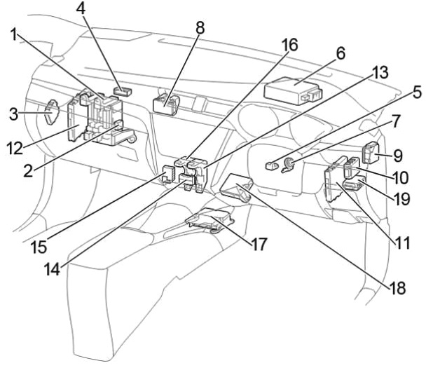
Assignment
- Fuse Box / Body ECM
- Additional fuse box
- Active light control unit (AFS) / Headlight range control unit (without AFS)
- Distribution connector
- Steering lock actuator
- Power steering control unit
- Key transponder amplifier
- Distribution block
- Distribution block
- Wiper relay
- Power control unit
- Control unit for the “Start-Stop” system
- Relay box No. 1
- Distribution connector
- Distribution connector
- Relay box No. 2
- Airbag control unit
- Air conditioner amplifier
- RHD: Double Door Lock Relay
Fuse box
It is located in the passenger compartment under the panel on the left side.
Access to box
LHD
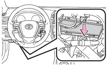
RHD
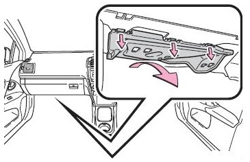
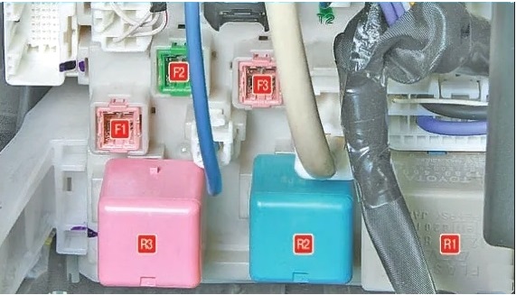
Photo – example

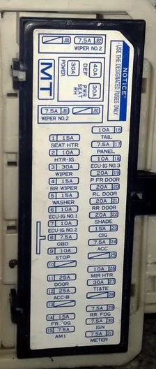
Diagram from the box cover
Diagram

Protected components
| 1 | 7.5А AM1 – Starting system, fuses: “ACC”, “CIG”, “ECU-IG NO.2”, “HTR-IG”, “WIPER”, “RR WIPER”, “WASHER”, “ECU-IG NO.1 “,” ECU-IG NO.3 “,” SEAT HTR “ |
| 2 | 15A FR FOG – Before February 2013, from May 2015: Fog lights |
| 7,5A FR FOG – February 2013 – May 2015: Fog lights | |
| 3 | 7,5A DRL – Daytime running lights |
| 4 | 25A ACC-B – Fuses: “CIG”, “ACC” |
| 5 | 25A DOOR – Door lock system, double locking system |
| 6 | – |
| 7 | 10A STOP – Stop lights, high stop light, anti-lock braking system, VSC +, multiport fuel injection system / sequential multiport fuel injection system, automatic transmission, shift lock system, starting system |
| 8 | 7,5A OBD – Diagnostic connector |
| 9 | 10A ECU-IG NO.2 – Reversing lights, charging system, hazard warning lights, rear window defogger, front passenger seat belt not fastened indicator, “PASSENGER AIRBAG” indicator, air conditioning system, AFS, rear view display system, assistance system sensor parking lot Toyota |
| 10 | 10A ECU-IG NO.1 – Main ECU Body, Intelligent Entry and Start System, Electric Cooling Fans, Shift Lockout System, Panoramic Roof Curtain, Auto Anti-Glare Interior Rearview Mirror, Anti-lock Braking System, Steering Sensor, yaw rate and overload sensor, VSC +. headlight cleaner. emergency preparation system. LKA. driver support system |
| 11 | 15A WASHER – Windshield washer, rear window washer |
| 12 | 15A RR WIPER – Rear wiper |
| 13 | 30A WIPER – Windshield wipers, rain sensor |
| 14 | 10A HTR-IG – Air conditioning system |
| 15 | 15A SEAT HTR – Before May 2015: Seat heaters |
| 20A SEAT HTR – From May 2015: Seat heaters | |
| 16 | 7,5A METER – Instrument Cluster |
| 17 | 7.5A IGN – Steering lock system, SRS airbag system, multiport fuel injection system / sequential multiport fuel injection system, automatic transmission, starting system |
| 18 | 7,5A RR FOG – Rear fog lamp |
| 19 | – |
| 20 | 30A TI&TE – Adjusting the tilt and departure of the steering wheel |
| 21 | 10A MIR HTR – Heated outside rearview mirrors |
| 22 | – |
| 23 | 7.5A ACC – Outside Rearview Mirrors, Shift Lock System, Audio System, ECU Main Body, Electrical Outlet |
| 24 | 15A CIG – Cigarette lighter |
| 25 | 20A SHADE – Panoramic roof blind |
| 26 | 20A RR DOOR – Rear right power window |
| 27 | 20A RL DOOR – Rear left power window |
| 28 | 20A P FR DOOR – Window regulator, front passenger side |
| 29 | 10A ECU-IG NO.3 – Toyota Parking Aid Sensor, AFS, Heated Windshield Wiper Area, Electric Parking Brake, Safety Belt with Pre-Crash System, Shift Paddles, Tilt & Ride Steering Wheel Adjustment, Electric Power Steering |
| 30 | 7,5A PANEL – Air Conditioning Switch, Audio System, Multidrive or Automatic Transmission Shift Lever Illumination, Glove Box Illumination, Manual Airbag On / Off System, Hazard Alarm, Cigarette Lighter, Headlight Washer Switch, AFS OFF Switch, Limiter Remover speed control, headlamp leveling switch, headlight height control switch, “VSC OFF” switch, Toyota parking aid switch, “LKA” switch, seat heating switch, “SPORT” switch, outside rearview mirror switches, sunroof release button fuel filler neck |
| 31 | 10A TAIL – Front side lights, rear lights, license plate lights, rear fog light, front fog lights, manual headlight height adjuster, instrument panel lights |
The fuse number 24 at 15A is responsible for the cigarette lighter. Another fuse responsible for the operation of the power outlets is located in the box under the hood.
Upper section of the box
To access it, you need to remove the panel protection for left-hand drive models.

Or a glove compartment for right-hand drive models.

Diagram
Appointment
| F1 | 30A POWER – Body ECU / Window Electrician |
| F2 | 30 / 40A DEF – Relay power supply – turn signal interrupter / Heated rear window, fuse: “MIR HTR” |
| F3 | 30A PWR SEAT – Power Seat |
| R1 | Relay – turn signal interrupter |
| R2 | Heater relay |
| R3 | Relay “IG1” – ignition system |
Additional fuse box
Diagram

Decoding
- 7,5A WIPER NO.2 – Charging system, ECU module for driver support system
- Reserve
Relay box No. 1
Relay box number 1 and number 2 are next to each other, see diagram.

Diagram

Designation
| R1 | Before Jun 2010: Front fog light (FR FOG) |
| From October 2016: Interior lighting (DOME CUT) | |
| R2 | – |
| R3 | Before November 2011: Instrument panel |
| From November 2011: Daytime Running Lights (DRL) | |
| R4 | Socket (ACC SOCKET) |
Relay box No. 2
Diagram
Assignment
| R1 | Starter (ST) |
| R2 | Rear fog light (RR FOG) |
| R3 | Auxiliary relay (ACC) |
| R4 | June 2010 – May 2015: Front fog light (FR FOG) |
| From October 2016: Heated area of the windscreen wiper blades (FR DEICER) |
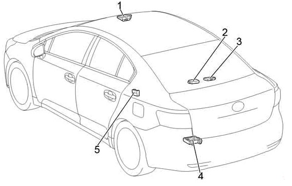
Additional elements
Diagram
Sedan
Wagon

Designation
- Pre-Crash Safety Sensor
- Tire pressure monitoring system control unit
- Central locking receiver
- Parking brake control unit
- Distribution connector
- Sunroof control unit
Engine compartment
Location
General arrangement of boxes under the hood

Appointment
- Skid Control ECU
- Fuse and relay box
- The engine control unit
- Glow plug control unit
- Glow plug relay
- Transmission control unit
- Headlight wiper relay
- Injector control unit
- LHD: Relay box
- RHD: Relay box
Fuse and relay box
Photo – example

Diagram
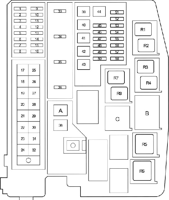

Protected components
| 1 | 10A DOME – Trunk / Trunk Lighting, Individual Mirror Lights, Engine Switch Lights, Front Door Lights, Personal / Interior Lights, Personal Lights, Footwell Lights |
| 2 | 15 / 20A RAD NO.1 – Audio system |
| 3 | 10A ECU-B – Instruments and gauges, main body ECU. steering sensor, warning light, double locking system, remote control, intelligent entry and start system, steering wheel tilt and reach adjustment |
| 4 | D.C.C |
| 5 | 10A ECU-B2 – Intelligent Entry & Start System, Air Conditioning System, ID Code Module, Power Windows, Power Seat Adjustment |
| 6 | 7,5A EFI MAIN NO.2 – Multiport fuel injection system / sequential multiport fuel injection system |
| 7 | 25A DOOR NO.2 – Before May 2015: Door lock system |
| 7,5A BODY ECU – From May 2015: Body ECU | |
| 8 | 30A AMP – Audio system |
| 9 | – |
| 10 | 20A STRG LOCK – Steering lock system |
| 11 | 20A A / F – Exhaust System |
| 12 | 30A AM2 – Starting system |
| 13 | 10A ETCS – Electronic Throttle Control System |
| 14 | 10A TURN-HAZ – Direction indicators, hazard warning lights |
| 15 | 7,5A ALT-S – Charging system |
| 16 | 7,5A AM2 NO.2 – Starting system |
| 17 | 50A HTR – Air conditioning system |
| 18 | 50A ABS NO.1 – ABS, VSC |
| 19 | 30A CDS FAN – Cooling fan |
| 20 | 40A RDI FAN – Cooling fan |
| 21 | 30A H-LP CLN – Headlight cleaners |
| 22 | 120A IP / JB – Fuses: “ECU-IG NO.2”, “HTR-IG”, “WIPER”, “RR WIPER”, “WASHER”, “ECU-IG NO.1”, “ECU-IG NO. 3 “,” SEAT HTR “,” AM1 “,” DOOR “,” STOP “,” FR DOOR “,” POWER “,” RR DOOR “,” RL DOOR “,” OBD “,” ACC-B “,” RR FOG “,” FR FOG “,” DEF “,” TAIL “,” SUNROOF “,” DRL “ |
| 23 | – |
| 24 | – |
| 25 | – |
| 26 | 50A H-LP MAIN – Fuses: “H-LP LH LO”, “H-LP RH LO”, “H-LP LH HI”, “H-LP RH HI” |
| 27 | 50A P / I – Fuses: “EFI MAIN”, “HORN”, “IG2”, “EDU” |
| 28 | 50A EFI MAIN – Before May 2015: Multiport fuel injection system / sequential multiport fuel injection system, “EFI NO.1”, “EFI NO.2” fuses |
| 50A FUEL HTR – From May 2015: Fuel heating | |
| 29 | 30A P-SYSTEM – Before May 2015: VALVEMATIC System |
| 50A EPKB – From May 2015: Electric parking brake | |
| 30 | 80A GLOW – Before May 2015: Engine Glow System |
| 80A EPS – From May 2015: Electric power steering | |
| 31 | 80A EPS – Before May 2015: Electric power steering |
| 80A GLOW – From May 2015: Engine Glow System | |
| 32 | 140A ALT – Before May 2015: Fuses: “RDI FAN”, “CDS FAN”, “H-LP CLN”, “PWR SEAT LH”, “FUEL OPN”, “ABS NO.1”, “ABS NO.2” , “FR DEICER”, “PSB”, “HTR”, “STV HTR”, “PWR OUTLET”, “HTR SUB NO.1”, “HTR SUB NO.2”, “HTR SUB NO.3”, “ECU -IG NO.2 “,” HTR-IG “,” WIPER “,” RR WIPER “,” WASHER “,” ECU-IG NO.1 “,” ECU-IG NO.3 “,” SEAT HTR “,” AM1 “,” DOOR “,” STOP “,” P FR DOOR “,” POWER “,” RR DOOR “,” RL DOOR “,” OBD “,” ACC-B “,” RR FOG “,” FR FOG ” , “TI & TE”, “SHADE”, “PWR SEAT RH”, “DEF”, “TAIL”, “DRL” |
| 120A ALT – Before May 2015: Fuses: “RDI FAN”, “CDS FAN”, “H-LP CLN”, “PWR SEAT LH”, “FUEL OPN”, “ABS NO.1”, “ABS NO.2” , “FR DEICER”, “PSB”, “HTR”, “STV HTR”, “PWR OUTLET”, “HTR SUB NO.1”, “HTR SUB NO.2”, “HTR SUB NO.3”, “ECU -IG NO.2 “,” HTR-IG “,” WIPER “,” RR WIPER “,” WASHER “,” ECU-IG NO.1 “,” ECU-IG NO.3 “,” SEAT HTR “,” AM1 “,” DOOR “,” STOP “,” P FR DOOR “,” POWER “,” RR DOOR “,” RL DOOR “,” OBD “,” ACC-B “,” RR FOG “,” FR FOG ” , “TI & TE”, “SHADE”, “PWR SEAT RH”, “DEF”, “TAIL”, “DRL” | |
| 33 | 15A IG2 – Before May 2015: Fuses: “IGN”, “METER” |
| 30A FUEL PUMP – From May 2015: Fuel pump | |
| 34 | 15A HORN – Sound signal |
| 35 | 30A EFI MAIN – Before November 2011: Multiport fuel injection system / sequential multiport fuel injection system, fuses: “EFI NO.1”, “EFI NO.2 |
| 10A FUEL OPN – From November 2011: Fuel filler flap | |
| 36 | 20A EDU – Until May 2015: Multiport fuel injection system / sequential multiport fuel injection system |
| 15A IGT / INJ – Before May 2015: Multiport fuel injection system / sequential multiport fuel injection system, ignition system | |
| 15A IGT / INJ – From May 2015: Fuses: “IGN”, “METER” | |
| 37 | 50A EFI MAIN – From May 2015: Fuses: “EFI NO.1”, “EFI NO.2”, “EFI NO.4” |
| 38 | 30A E-PKB – Before May 2015: Electric parking brake |
| 40A BBC – From May 2015: Start-Stop System | |
| 39 | 30A HTR SUB NO.3 – Before May 2015: Auxiliary heater |
| 40 | – |
| 41 | 30A HTR SUB NO.2 – Before May 2015: Auxiliary heater |
| 42 | 50A HTR – From May 2015: Air Conditioning System |
| 43 | 30A HTR SUB NO.1 – Before May 2015: Auxiliary heater |
| 50A HTR SUB NO.1 – From May 2015: Auxiliary heater | |
| 44 | 30A PWR SEAT LH – Electric seat, lumbar support |
| 45 | 25A STV HTR – Auxiliary heater |
| 46 | 30A ABS NO.2 – ABS, VSC |
| 47 | 20A FR DEICER- Heated area of the wiper blades of the windshield |
| 48 | 10A FUEL OPN – Fuel filler flap |
| 49 | 30A PSB – Safety belt with pre-crash system |
| 50 | 15A PWR OUTLET – Socket / Cigarette Lighter |
| 51 | 10А H-LP LH LO – Left headlight (low swat) / 15A HID lamps (HID): Left headlight (low swat) |
| 52 | 10А H-LP RH LO – Right headlight (low beam) / 15A HID lamps: Right headlamp (dipped swath) |
| 53 | 10A H-LP LH HI – Left headlamp (high beam) |
| 54 | 10A H-LP RH HI – Right headlamp (high beam) |
| 55 | 10A EFI NO.1 – Distributed fuel injection system/sequential distributed fuel injection system, air flow meter, exhaust system |
| 7,5A EFI NO.1 – Distributed fuel injection system/sequential distributed fuel injection system, air flow meter, exhaust system | |
| 56 | 10A EFI NO.2 – Air intake system, air flow meter, exhaust system |
| 15A EFI NO.2 – Air intake system, air flow meter, exhaust system | |
| 57 | 7,5A IG2 NO.2 – Starting system |
| 58 | 7,5A EFI NO – Distributed fuel injection system/sequential distributed fuel injection system, fuses: ‘EFI NO.1’, ‘EFI NO.2’ |
| 59 | 5A CDS EFI – Cooling fan |
| 60 | 7,5A EFI NO.3 – Distributed fuel injection system/ sequential distributed fuel injection system |
| 5A RDI EFI – Cooling fan | |
| Relay | |
| R1 | Before November 2013: Heated wiper blades / brake lights (FR DEICER / BRAKE LP) |
| From November 2013: Cooling fan (FAN NO.2) | |
| R2 | Cooling fan (FAN NO.3) |
| R3 | Before May 2015: Air Fuel Ratio (A / F) Sensor |
| From May 2015: Fog lamp (FR FOG LH) | |
| R4 | Before May 2015: Interior lighting (DOME CUT) |
| From May 2015: Fog lamp (FR FOG RH) | |
| R5 | Engine control unit (EFI MAIN) |
| R6 | Headlights (H-LP) |
| R7 | Before Nov 2013: Cooling fan (FAN NO.2) |
| November 2013 – October 2016: Heated area of the windscreen wiper blades (FR DEICER) | |
| From October 2016: Dimmer | |
| R8 | Cooling fan (FAN NO.1) |
| R9 | May 2015 – October 2016: Interior lighting (DOME CUT) |
| From October 2016: (TSS C HTR) | |
| R10 | Before Nov 2011: Fuel filler flap (FUEL OPN) |
| R11 | Before Nov 2011: Dimmer |
| From November 2011: | |
| without AFS: Dimmer | |
| From November 2011: | |
| AFS: – | |
| May 2015 – Oct. 2016: | |
| with fuel heating (P / t): Fuel heating (FUEL HTR) | |
| without fuel heating: – | |
| R12 | From November 2011: |
| AFS: Dimmer | |
| May 2015 – October 2016: Dimmer | |
Relay box
Diagram
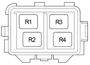
Designation
| R1 | – |
| R2 | Auxiliary heater (HTR SUB NO.1) |
| R3 | Auxiliary heater (HTR SUB NO.2) |
| R4 | Auxiliary heater (HTR SUB NO.3) |
If you have something to add – write in the comments.
Hello,
I am interested in location of the starter relay Toyota Avensis T27 2009 RHD 2.0 diesel.
And subject fuses. The car doesn’t start. Starter is ok. Ignition is ok. Thank you
Hello,
I am interested in location of the starter relay Toyota Avensis T27 2010 RHD 2.0 diesel.
And subject fuses. The car doesn’t start. Starter is ok. Ignition is ok. Thank youWiring diagrams online