Toyota Sprinter was produced with different body options, such as Toyota Sprinter Trueno (three-door coupe), Toyota Sprinter Cielo five-door liftback), Toyota Sprinter Carib (station wagon), Toyota Sprinter Marino (five-door hardtop) and others. Also known as Geo Prizm or Chevrolet Prizm. In this article we will show the description of fuses and relays Toyota Sprinter 1987, 1988, 1989, 1990, 1991, 1992, 1993, 1994, 1995, 1996, 1997, 1998, 1999, 2000, 2001 release with box diagrams and their locations. Highlight the cigarette lighter fuse.

The location of the boxes and the purpose in them may differ from the one presented and depend on the year of manufacture, the level of equipment and the region of delivery of your car. Check the assignment with your diagrams on the box cover.
Contents
Passenger compartment
Type 1
This diagram is suitable for models in the 90, 91 – 95 body. The unit is located under a panel on a rack behind a protective cover.

Diagram from the box cover. Option 1.

Diagram from the box cover. Option 2.

Assignment
- ECU-IG – electronic fuel injection system, cabin air cooling system
- STOP – light stop signal
- RADIO – radio, electric rear-view mirror
- ECU-B – rear fog lamp
- ENGINE – battery charging system, engine heating system
- WIPER – cleaners and washers for glass and headlights
- CIG – cigarette lighter, digital clock display
- IGN – battery charging system, charging indicator lamp, exhaust gas recirculation device, electric fan in the engine compartment, engine preheating
- TAIL – dimensions, license plate light, instrument panel lighting
- GAUGE – indicator devices, control, warning lights, driving efficiency control device, reverse light, air conditioning control system, heated rear window, electric window, central locking
- TURN – flashing direction indicators, hazard warning lights
- SUNROOF is an electrically operated sliding roof.
The cigarette lighter fuse is designated CIG.
Type 2
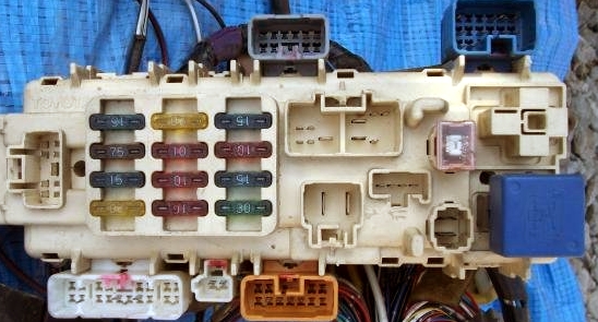
This diagram is suitable for models in the 100, 101 body. As in the previous version, the unit is mounted under the panel on a pillar, near the driver’s foot.

Block example
 Diagram

Protected components
Right hand drive
| 1 | 15A FOG – fog lights |
| 2 | 10A IGN – ignition |
| 3 | 15А STOP – brake lights |
| 4 | 30А DEFOG – glass heater |
| 5 | 20А CIG & RADIO – cigarette lighter, radio tape recorder, mirrors |
| 6 | 10А ECU-В – ABS, power supply of the central lock |
| 7 | 10A TURN – direction indicators |
| 8 | 10А GAUGE – devices |
| 9 | 15A TAIL – dimensions |
| 10 | 7.5А DEF-I / UP – increase in idle speed when the glass heater is turned on |
| 11 | 15А ECU-IG – transmission electronics, ABS, control system lock (automatic transmission) |
| 12 | 20А WIPER – wipers |
Left hand drive
| 1 | 15A FOG – fog lights |
| 2 | 10A IGN – ignition |
| 3 | 15А STOP – brake lights |
| 4 | 20А SEAT HTR – seat heater |
| 5 | 20А CIG & RADIO – cigarette lighter, radio tape recorder, mirrors |
| 6 | 10А ECU-В – ABS, power supply of the central lock |
| 7 | 10A TURN – direction indicators |
| 8 | 10А GAUGE – devices |
| 9 | 10 / 15A TAIL – dimensions |
| 10 | 7.5А DEF-I / UP – increase in idle speed when the glass heater is turned on |
| 11 | 15А ECU-IG – transmission electronics, ABS, control system lock (automatic transmission) |
| 12 | 20А WIPER – wipers |
The fuse number 5, 20A, is responsible for the cigarette lighter.
Relay designation
- a – POWER – glass lifters, sunroof and central locking
- b – FOG – fog lights
- c – FLASHER – relay – breaker
- A – DEFOG – glass heater
- B – TAIL – dimensions
Type 3
This diagram is suitable for 110, 111 body models. In this version, the fuse box is located at the bottom of the dashboard.

Photo – example

Diagram

Appointment
| 1 | 15А FOG – Fog lights |
| 2 | 15A STOP – Stop lights, fuel injection system, anti-lock brake system, shift lock system |
| 3 | 10A ECU -IG – Anti-lock braking system |
| 4 | 5А STARTER – Starter |
| 5 | 15А LIGHTER – Cigarette lighter, clock, electric mirrors, radio tape recorder |
| 6 | 5A ECU -B – Diesel engine electronic control system |
| 7 | 10A METER – Instrument cluster |
| 8 | 7,5А TURN – Direction indicators, alarm |
| 9 | 7,5A IGNITION – Battery charging system, fuel injection system |
| 10 | 15A TAIL – Taillights, tail lamps, license plate illumination, instrument cluster and audio system |
| 11 | 20А WIPER – Windscreen wipers and washer |
| 12 | 30А DEFOG – Heated rear window |
| 13 | 10A IDLE-UP – System for increasing idle speed |
| 14 | 30А DOOR – Central locking |
The fuse number 5, 15A, is responsible for the cigarette lighter.
Engine compartment
The main fuse and relay box is located under the hood on the left side.
Type 1
Photo – example

Diagram from the box cover

Circuits protected
- CHARGE 7,5A – battery charging system, indicator lamp for charging current, starting automatic
- FAN-I / UP 7,5A – pre-start engine heating system, automatic start-up
- HORN – signal relay
- HEAD – headlight relay
- DOME 10A – ceiling lamp, door warning lamps, tailgate lamp
- EFI 15A – electronic petrol injection system
- HAZ-HORN 15A – warning flashing signals, sound signal
- FAN 30A – engine cooling system, fan
- FAN NO.1 – cooling fan relay.
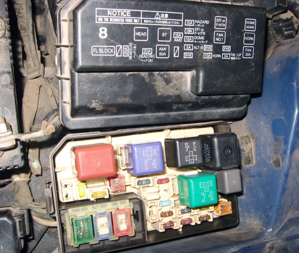
Type 2

Legend from the cover

Diagram

Designation
| a | 30A AM2 – AM2 circuit of the ignition switch (terminals IG2, ST2) |
| b | 30A FAN – radiator fan |
| c | 40A AM1 – output circuit AM1 of the ignition switch (terminals ACC, IG1, ST1), 80A GLOW (diesel) – candles |
| d | 80 / 100A ALT (gasoline) – battery charging, AM1 (diesel), AM1 (2E) |
| e | 50A ABS – ABS |
| 1 | 20А DOME – electric drive and interior lighting |
| 2 | 20А HA7-HORN – alarm, sound signal |
| 3 | 7,5А FAN-I / UP – increase in idle speed |
| 4 | 7.5A ALT-S – charging |
| 5 | 7,5A Spare – spare |
| 6 | 15A Spare – spare |
| 7 | 20A Spare – spare |
| 8 | 15A HEAD (RH) – right headlights |
| 9 | 15А HEAD (LH) – left headlights |
| 10 | 15A EFI F-HTR – fuel supply |
| A | HORN – Signal relay |
| B | FAN – Cooling fan relay |
| C | E / G-MAIN – Main relay |
| D | HEAD – Headlight relay |
| E | EFI – Motor relay |
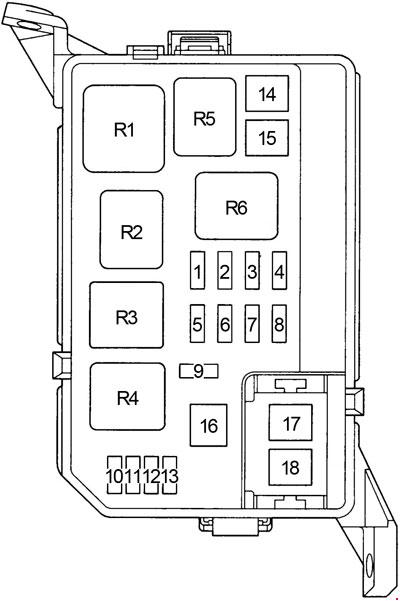
Type 3
Photo – an example and a diagram from the block cover
Diagram
Assignment
| 1 | 5А ALT-S – Charging system |
| 2 | 10A HEAD (RH-UPR) – Right headlight (DRL – daytime running lights) |
| 3 | 15A EFI – 4A-FE, 5A-FE, 7A-FE, 4E-FE: Multiport fuel injection system / sequential multiport fuel injection system |
| 15A F-HTR – 2C-E: Multiport fuel injection system / sequential multiport fuel injection system | |
| 4 | 10А HORN – Sound signal, anti-theft system |
| 5 | 10А HAZARD – Hazard warning system, direction indicators |
| 6 | 15A AM2 – Starting system, fuses: “ST”, “IGN” |
| 7 | – |
| 8 | 10A HEAD (LH-UPR) – Left headlight (DRL – daytime running lights) |
| 9 | 15А DOME – Audio system, interior lighting, personal lighting, luggage compartment lighting, clock, daytime running lights, anti-theft system |
| 10 | – |
| 11 | – |
| 12 | – |
| 13 | – |
| 14 | 50А AM1 – Fuses: “CIG”, “TURN”, “GAUGE”, “ECU-IG”, “WIP” |
| 15 | 30A FAN – Cooling fan |
| 30A RDI – Cooling fan | |
| 16 | 40A MAIN – Starting system, fuses: ”HEAD (LH) or HEAD (LH-UPR),” HEAD (RH) or HEAD (RH-UPR), ”HEAD LH-Lo” and ”HEAD RH-LO” |
| 17 | 100А ALT – Fuses: “RDI”, “CDS”, “AM1”, “POWER”, “D / L”, “TAIL”, OBD, “FOG”, “ECU-B”, “STOP”, “DEF” , “HTR” |
| 18 | 50A ABS – ABS |
Relay
| R1 | Engine control unit (ENGINE MAIN) |
| R2 | 4A-FE, 5A-FE, 7A-FE, 4E-FE: Engine control unit (EFI) 2C-E: Fuel heating (F-HTR) |
| R3 | Headlights (HEAD) |
| R4 | Starter (ST) |
| R5 | Sound signal |
| R6 | Cooling fan (FAN NO.1) |
Schemes do not fit or you need more information – read this material.
Am having issues with my Toyota sprinter 1992 model, power windows not working, need info on how much voltage to main control.