Toyota Land Cruiser 100 and Toyota Land Cruiser 105 were produced in 1998, 1999, 2000, 2001, 2002, 2003, 2004, 2005, 2006, 2007. During this time, the model has been restyled. In this publication, we will show the location of the electronic control units, a description of the fuses and relays of the Toyota Land Cruiser 100 (105) with box diagrams and their locations. Highlight the cigarette lighter fuse.

The location of the boxes and the purpose of the elements in them may differ from that shown and depends on the year of manufacture and the region of delivery.
Contents
Passenger compartment
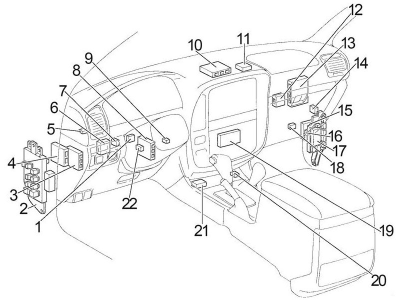
Location
General layout of blocks in the cabin
Left hand drive (1998 – 2002)
Left hand drive (2003 – 2007)

RHD

Assignment
- ’98-’03: Turn Signal Flasher
- ’98-’03: Fuse Box
’03-’07: Fuse Box / Body ECU - ’98-’03: ABS ECU
- Tilt and Telescopic ECU
- Transponder Key Computer
- ’98-’03: Wireless Door Lock ECU
- ’98-’03: ECT ECU
- ’98-’03: Suspension Control ECU
- Transponder Key Amplifier
- ’98-’03: Instrument ECU
- Theft Deterrent ECU
- Auto Antenna Relay
- Engine and ECT ECU
- Center Differential Lock Control Relay
- ’98-’03: Front/Rear Lock Control ECU
or Rear Lock Control ECU - ’98-’03: Cruise Control ECU
- ’98-’03: Junction Block (MTR Relay)
’03-’07: Fuse Box - ’98-’03: Viscous Heater Amplifier
- ’98-’03: Center ECU
- ’98-’03: ABS Deceleration Sensor
- Center Airbag Sensor Assembly
- ’98-’03: AHC Main Relay
- ’98-’03: RHD: Pre-Heating Timer
- ’03-’07: A/C Control (with Navigation System)
- ’03-’07: Junction Block
- ’03-’07: Junction Block
- ’03-’07: Junction Block
- ’03-’07: Junction Block
- ’03-’07: Gateway ECU
- ’03-’07: Shift Lock Control ECU
- ’03-’07: A/C Control (without Navigation System)
- ’03-’07: ABS & BA & TRAC & VSC ECU
Left side fuse box

In the general diagram, it is indicated by number 2 and located on the left side under the instrument panel.
Check the assignment against your schematics on the cover of the units.

Photo of fuse box
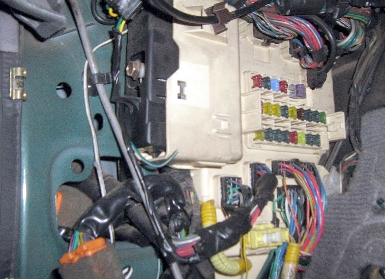
Diagram. Type 1.
1998 – 2002

Circuits protected
| 1 | 10A MIRR – Power mirrors |
| 2 | 15A SRS – Airbags, seat belts with pretensioner |
| 3 | 15A CIGAR – Cigarette lighter, audio system, antenna |
| 4 | 10A IGN – Multiport fuel injection system / sequential multiport fuel injection system, ABS, airbags, seat belts with pretensioner, low warning light |
| 5 | 40A POWER – Central locking, power windows, sunroof, power seats, tilt and height adjustment of the steering column |
| 6 | 10A DOME – Interior lighting, personal lighting |
| 7 | 20A AHC-IG – Active body height control (AHC) |
| 8 | 20A DIFF – Differential lock control unit |
| 9 | 15A GAUGE – Instrument cluster, service and warning lights, warning buzzer, reversing lamps, air conditioning, transmission control unit, daytime running lights, wireless control system |
| 10 | 20 / 25A WIPER – Wiper and washer, rear window wiper and washer |
| 11 | 7,5A I / UP – Engine Idle System |
| 12 | 15A FR FOG – Front fog light |
| 13 | 15A STOP – Brake light bulbs, additional brake light |
| 14 | 30A RR A.C – Rear air conditioner |
| 15 | 20A DEFOG – Heated rear window |
| 16 | 15A ECU-B – Steering column tilt and height adjustment system, daytime running lights, anti-theft system |
| 17 | 15A TAIL – Side light, license plate light, instrument panel light |
| 18 | 15A AHC-B – Active body height control (AHC) |
| 19 | 10A OBD – Diagnostic connector |
| 20 | 10A RR HTR – Rear heater |
| 21 | 15A ECU-IG – ABS, Transmission Selector Lock, Power Seats, Aerial, Tilt & Height Adjustment Steering Column |
| 22 | 15A PWR OUTLET – Socket |
For the operation of the cigarette lighter and the socket, fuses number 3 and 22 at 15A are responsible.
Some relays are attached to the back of the unit.
Scheme

Designation
| R1 | Circuit opening (Fuel pump (C/OPN)) |
| R2 | Fuel pump (FUEL/PMP) |
| R3 | (D/L (L)) |
| R4 | (SPIL/VLV) |
| R5 | Starter (ST/CUT) |
| R6 | (D/L (U)) |
| R7 | Front fog light (FR FOG) |
| R8 | – |
| R9 | Rear windshield defogger (DEFOG) |
| R10 | Power windows, electric moon roof (POWER) |
| R11 | Rear heater (RR HTR) |
| R12 | Interior lights (DOME) |
| R13 | Tail lights (TAIL) |
Diagram. Type 2.
2003 – 2007

Protected components
| 1 | 15A PWR OUTLET – Socket |
| 2 | 15A CIG – Cigarette lighter |
| 3 | 7,5A ACC – Illumination of the instrument panel |
| 4 | 7.5A AM1 – Multiport fuel injection system / sequential multiport fuel injection system |
| 5 | 20A DEFOG – Heated rear window |
| 6 | 15A AHC − B – Active body height control (AHC) |
| 7 | 20A FUEL HTR – Fuel heating |
| 8 | 7,5A POWER HTR – Auxiliary heater |
| 9 | 20A AHC − IG – Active body height control (AHC) |
| 10 | 10A EFI NO.2 – Emission Reduction System |
| 10A ECD NO.2 – Emission Reduction System | |
| 11 | 10A GAUGE1 – Instrument Cluster |
| 12 | 10A ECU-IG1 – Multiport fuel injection system / sequential multiport fuel injection system |
| 13 | 10A ECU − B1 – Navigation system |
| 14 | 15A DBL LOCK – Double locking system |
| 15 | 30A BATT CHARGE – Trailer charging system |
| 16 | 15A A / C – Air Conditioning |
| 17 | 15A STOP – Brake light |
| 18 | 7,5A OBD − 2 – Diagnostic connector |
| 19 | 7,5A IDEL UP – Engine idle system |
| 20 | 30A LH SEAT – Power left seat |
| 21 | 25A DOOR – Central locking, power windows |
| 22 | 25A SUN ROOF – Hatch |
| 23 | 15A RR WIPER – Rear wiper |
For the operation of the cigarette lighter and the socket, fuses number 1 and 2 at 15A are responsible.
Relay circuit on the back of the unit

Functions
- R1 – Heated rear window (DEFOG)
- R2 – Ignition (IG1 NO.2)
- R3 – Ignition (ACC)
- R4 – Interior lighting (DOME)
Right side fuse box
In the diagram it is designated as number 17. Located under the dashboard.
Diagram
2002 – 2007

Appointment
| 1 | 10A ECU − B2 – Central locking, power windows |
| 2 | 20A DIFF – All-wheel drive system |
| 3 | 15A WASHER – Washer for glass |
| 4 | 10A RADIO – Audio system |
| 5 | 10A DOME – Interior lighting |
| 6 | 40A VGRS – Variable Ratio Steering |
| 7 | 20A P / W (FL) – Front Left Power Window |
| 8 | 20A P / W (RL) – Rear Left Power Window |
| 9 | 25A WIPER – Wiper |
| 10 | 10A ECU − IG2 – Rear air conditioner |
| 11 | 15A SEAT HTR – Heated seats |
| 12 | 10A GAUGE2 – Reversing lamps |
| 13 | 7,5A MET – Instrument cluster |
| 14 | 7,5A ING – Multiport fuel injection system / sequential multiport fuel injection system |
| 15 | 7,5A SECURITY – Anti-theft system |
| 16 | 20A P / W (RR) – Rear Right Power Window |
| 17 | 20A P / W (FR) – Front Right Power Window |
| 18 | 30A BATT CHARGE – Trailer charging system |
| 19 | – |
| 20 | 20A TIL & TEL – Steering column tilt and height adjustment system |
| 21 | 30A RR A / C – Rear air conditioner |
| 22 | 30A RH SEAT – Power Right Seat |
Relay circuit on the back of the unit

Decoding
- R1 – Stop lamps (STOP LP)
- R2 –
- R3 – Ignition (IG1 NO.3)
- R4 – Ignition cut (ACC CUT)
Additional elements
Diagram

Assignment
- Moon Roof Control ECU
- RHD: Remote Control Mirror ECU
- Stereo Component Amplifier
- A/C Amplifier
- Rear Cooler Relay
- Liftgate Type: Rear Wiper Relay
- Towing Hitch Relay
- Towing Converter Relay
- Fuel Pump Control ECU
- Fuel Pump Select Relay
- Sub Fuel Pump Forcing Driving Relay
- ’03-’07: Television Camera ECU
- ’03-’07: Navigation ECU
- Rear Heater Relay
- Control Valve Assembly
- LHD: Remote Control Mirror ECU
- Swing Type: Rear Wiper Relay RH
- Swing Type: Rear Wiper Relay LH
Engine compartment
Location
General arrangement of blocks under the hood

Designation
- Injector Driver (EDU)
- Winch Main Relay
- Glow Plug Relay
- Fuse Box
- Fusible Link Block
- Headlight Control ECU LH
- Viscous Heater Relay
- Water Temperature Cut Relay
- A/C Condenser Fan Relay
- Headlight Cleaner Control Relay
- Headlight Control ECU RH
- Fusible Link Block (Cold Area)
- Daytime Running Light Relay No.3
- Intake Heater Relay
Fuse and relay box
Located on the left side, next to the battery.
Type 1

Diagram

Appointment
| Fuse | |
| 1 | 20A AM1 NO.2 – Starting system, direction indicators, alarm, fuses: “CIGAR”, “ECU-IG”, “MIRR”, “SRS” |
| 2 | 20A A.C – Air conditioner |
| 3 | 10A POWER HTR – Auxiliary heater |
| 4 | 15A SEAT HTR – Heated seats |
| 5 | 20A FUEL HTR – Fuel heating |
| 6 | 15A MIR HTR – Heated mirrors |
| 7 | 20A HEAD CLNER – Cleaners of headlights |
| 8 | 20A CDS FAN – Cooling fan |
| 9 | 20A EFI – Multiport fuel injection system / sequential multiport fuel injection system, emission control system, fuel pump |
| 20A ECD – Multiport fuel injection system / sequential multiport fuel injection system | |
| 10 | 10A HORN – Sound signal |
| 11 | 15A THROTTLE – Electronic throttle control system |
| 12 | 20A RADIO – Audio system |
| 13 | 15A HAZ-TRN – Hazard warning system, direction indicators |
| 14 | 30A AM2 – Starting system, multiport fuel injection system / sequential multiport fuel injection system, “IGN” fuse |
| 15 | 20A ECU-B1 – Central locking, power windows, rear wiper and washer, wireless control system, power mirrors, instrument cluster, air conditioning, automatic lighting system, anti-theft system |
| 16 | 20A HEAD (LH-UPR) – High beam left |
| 17 | 20A HEAD (RH-UPR) – High beam right |
| 18 | 10A HEAD (LH-LWR) – Low beam left, front fog light |
| 19 | 10A HEAD (RH-LWR) – Low beam right |
| 20 | 40A 1998-1999: ABS |
| 50A 2000-2003: ABS | |
| 21 | 50A AHC – Active body height control (AHC) |
| 22 | 50A ACC – Fuse “PRW OUTLET” |
| 23 | 80A AM1 NO.1 – Charging system, fuses: ”AM1 NO.2”, ”GAUGE”, ”WIPER” |
| 24 | 60A HTR – Air Conditioner |
| 25 | 80A GLOW – Engine preheating system |
| 26 | 40A ABS |
| 27 | 30A STARTER – Start system |
| Relay | |
| R1 | A / C Compressor Clutch (MG CLT) |
| R2 | Heated mirrors (MIR HTR) |
| R3 | Auxiliary relay (ACC) |
| R4 | Active body height control (AHC) |
| R5 | Ignition (IG1 NO.1) |
| R6 | Ignition (IG1 NO.2) |
| R7 | ABS (ABS SOL) |
| R8 | Engine control unit (EFI) |
| Engine control unit (ECD) | |
| R9 | Sound signal |
| R10 | Dimmer (light switch) |
| R11 | Starter |
| R12 | ABS (ABS MTR2) |
| R13 | Headlights (HEAD) |
| R14 | ABS (ABS MTR1) |
Type 2

Diagram
2003 – 2007

Protected components
| 1 | – |
| 2 | – |
| 3 | – |
| 4 | – |
| 5 | 7.5A ST1 – 2002-2005: Multiport fuel injection system / sequential multiport fuel injection system |
| 7.5A WIP − S – 2006-2007: – | |
| 6 | 30A TOWING – Trailer lighting |
| 7 | 15A MIR HTR – Heated mirrors |
| 8 | 10A RR HTR – Rear heater |
| 9 | 15A HAZ − TRN – Hazard warning lights, direction indicators |
| 10 | 7,5A ALT − S – Charging system |
| 11 | 20A NV − IR |
| 12 | 15A FR FOG – Fog light |
| 13 | 30A TOWING BRK – Trailer lighting (brake lights) |
| 14 | 20A HEAD CLNER – Cleaners of headlights |
| 15 | 10A FR − IG – Charging system |
| 16 | 7,5A PANEL – Illumination of the instrument panel |
| 17 | 30A TOWING TAIL – Trailer lighting (side light) |
| 18 | 15A TAIL – Side light |
| 19 | 30A BAT – Fuse: “ECU − B2” |
| 20 | 7,5A TEL – Phone |
| 21 | 30A AMP – Audio system |
| 22 | 25A EFI NO.1 – Multiport fuel injection system / sequential multiport fuel injection system |
| 25A ECD NO.1 – Multiport fuel injection system / sequential multiport fuel injection system | |
| 23 | 15A AM2 – Fuse: “IGN” |
| 24 | 10A ETCS – Multiport fuel injection system / sequential multiport fuel injection system |
| 25 | 10A HORN – Sound signal |
| 26 | – |
| 27 | 10A HEAD (RH − LWR) – Low beam right |
| 28 | 10A HEAD (LH − LWR) – Low beam left |
| 29 | 20A HEAD (RH − UPR) – High beam right |
| 30 | 20A HEAD (LH − UPR) – High beam left |
| 31 | 40A ABS |
| 32 | 50A ABS |
| 33 | 50A AHC – Active body height control (AHC) |
| 34 | 30A STARTER – Start system |
| 35 | SHORT PIN A – Fuses: “BAT”, “AMP” |
| 36 | SHORT PIN B – Fuses: “HAZ-TRN”, “ALT-S” |
| 37 | 80A GLOW – Engine preheating system |
| Relay | |
| R1 | Heater (HTR) |
| R2 | ABS (ABS MTR1) |
| R3 | ABS (ABS MTR2) |
| R4 | ABS (ABS SOL) |
| R5 | Engine control unit (EFI) |
| Engine control unit (ECD) | |
| R6 | Active body height control (AHC) |
| R7 | Fuel pump (C / OPN) |
| R8 | Fuel pump (F / PUMP) |
| R9 | Starter (ST) |
Relay
Diagram

Decoding
| R1 | Cooling system |
| R2 | Air conditioner compressor clutch (MG CLT) |
| R3 | Electric cooling fan (CDS FAN) |
| R4 | Horn |
| R5 | Headlight (HEAD) |
| R6 | High beam (HEAD HI) |
| R7 | Outside rear view mirror defogger (MIR HTR) |
| R8 | Rear heater (RR HTR) |
| R9 | Instrument panel (PANEL) |
| R10 | Front fog light (FR FOG) |
| R11 | Ignition (IG NO.1) |
| R12 | Tail lights (TAIL) |
Fusible link box
On the positive terminal of the storage battery, a fuse box made in the form of fusible links is attached.

Diagram

Assignment
Type 1
1998 – 2002
| 1 | 100A J / B NO.2 – Fuses: ”ECU-B”, ”FR FOG”, ”DEFOG”, ”AHC-B”, ”TAIL”, ”STOP”, ”DOME”, ”POWER”, ”OBD” , ”RR AC” and ”RR HTR” |
| 2 | 140A ALT – Fuses: “J / B NO.2”, “MIR HTR”, “AM1 NO.1”, “ACC”, “CDS FAN”, “HTR” and “ABS NO.1” |
| 3 | 100A MAIN – Fuses: “ECU-B”, “FR FOG”, “DEFOG ‘,” AHC-B “,” OBD “,” TAIL “,” STOP “,” DOME \ TOWER “,” RR AC “,” RR HTR “ |
| 4 | 7,5A ALT-S – Charging system |
Type 1
2003 – 2007
| 1 | 50A HTR – Air conditioner / heater |
| 2 | 120A J / B NO.1 – Relay “IG1 NO.1”, relay “TAIL”, fuses: “MIR HTR”, “RR HTR”, “TOWING BRK”, “TOWING”, “FR FOG” |
| 3 | 120A J / B NO.2 – Relay “IG1 NO.2”, relay “ACC”, fuses: “DEFOG”, “AM1”, “LH SEAT”, “STOP”, “ECU-B1”, “SUN ROOF” , “OBD-2”, “DOOR” |
| 4 | 120A J / B NO.3 – Relay “IG1 NO.3”, fuses: “SECURITY”, “TIL & TEL”, “RH SEAT”, “RR A / C”, “P / W (RR)”, ” P / W (RL) “,” P / W (FR) “,” P / W (FL) “ |
| 5 | 120A MAIN – Relay “HEAD HI”, relay “HEAD”, fuses: “ABS NO.1”, “ABS NO.2”, “SHORT PIN A”, “EFI OR ECD NO.1”, “SHORT PIN B” , “AM2”, “STARTER”, “HORN”, “ECTS” |
| 6 | 140A ALT – Fuses: “J / B NO.1”, “J / B NO.2”, “J / B NO.3”, “HTR” |
If you have any questions or have something to add – write in the comments.
Which relay is for the headlight adjuster switch
Why is it that all indicators from dash board interior to Head lights ,break, signal all out
Hi
I have a Toyota Land cruiser 105 series petrol 4.5ltr
: Cranks okay
: Sparks okay
:Fuel pump works
:But still won’t start???
I have a land cruiser all working well but the radio is not going off on off key hence, draining the battery. What could be the problem?
Hi I’m looking for rear cargo windows vent fuse lexus 470 landcruiser 100 series
I have a LHD 2000 cruiser and for some reason as of last night after a 20 minute test drive or so the CDS fan won’t turn off even with car off and key out. Have to pull the 20A fuse from the box under the hood drivers side. Slot 8 I believe
Is ok for me to get these whole pdf
I have land cruiser 101 serious
There’s when I turn off light(high beam and low beam) low beam not turn off, ahena I remove fuse only turn off light,I checked relay it’s work normally
Help me please
What is the issue
I Need the beam light relay and fuses of landcruiser 13 model and the cluster meter daigram
I have a Landcruiser Gx 2007. My dashboard stopped working after pressing a SUBtank button. What can I do to fix the problem. I’m blindly travelling.
He’ll Pardo 1997