Isuzu Elf is a series of commercial trucks manufactured by the Isuzu concern, which has been produced from 1954 to the present in six generations with various modifications and types of engines. Known outside of Japan as the N-series (NQR 75, NPR 71 and many others). In this article, we will present a description of the Isuzu Elf N-Series fuses and relays with fuse box diagrams, their locations and photo examples of performance for the 5th generation (1989, 1990, 1991, 1992, 1993, 1994, 1995, 1996, 1997, 1998, 1999, 2000 , 2001, 2002, 2003, 2004, 2005, 2006) and 6 generations (2007, 2008, 2009, 2010, 2011, 2012, 2013, 2014, 2015, 2016, 2017, 2018, 2019, 2020). Select the cigarette lighter fuse.
There is no one general description for all models. We will present the 3 most common options. Check the purpose of the fuses and relays with your diagram on the block cover.
Contents
Type 1
These diagrams are suitable mainly for the 5th generation and models with a 4HF1 and 4HG1 engine.
Fuse box
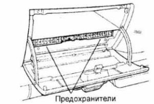
This block is located in the panel and is closed with a protective cover, on the reverse side of which an actual diagram with a description of the elements will be applied.
Photo

Diagram
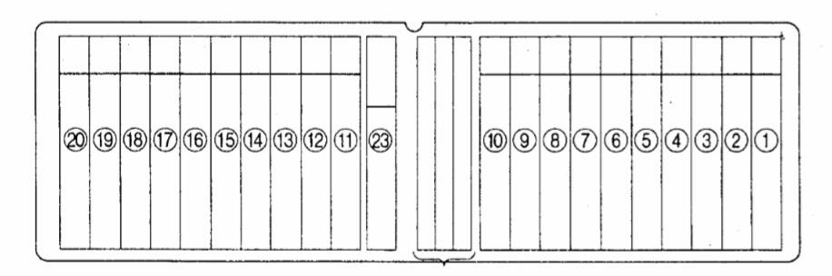
Designation
| 1 | 25А / 15А Heater fan motor, heater fan resistor, temperature switch, pressure switch, air conditioner shutdown relay, air conditioner relay, thermostat, e / p valve of the system for increasing the speed of rotation XX (FICD) |
| 2 | 10A Air conditioning switch, air conditioning relay, pressure switch, electromagnetic clutch of the air conditioning compressor, e / p valve of the system for increasing the speed of rotation XX (FICD), thermostat |
| 3 | 10A Starter relay, start inhibit switch |
| 4 | 15A Cigarette lighter, radio |
| 5 | 10A Headlamp (right), headlight switch relay |
| 6 | 10A Headlight (left), headlamp switch relay, turn signal relay, turn signal |
| 7 | 15A Radio and clock, interior lighting, interior lighting switch, door limit switches, reverse warning buzzer, door lock switch, central locking relay, electric door locks, central locking controller, speedometer |
| 8 | 15A Hazard Switch, Horn, Horn Relay, Horn Switch, Turn Signals |
| 9 | 15A Dimension relay, lights, fog light switch, fog lights, light control switch, rear fog light switch, rear fog light relay |
| 10 | 10A Brake light switch, brake lights, selector lock controller |
| 11 | 15A Wiper and Washer Control Switch, Wiper Motor, Washer Motor, Wiper Interval Relay |
| 12 | 10A Mountain brake control relay, automatic transmission electronic control unit, “OD OFF” indicator, “UNLADEN” indicator, condenser fan motor relay, reverse warning buzzer, reversing light switch, reversing lights, start inhibit switch, starter relay , engine start aids (QOSIII) controller,, engine start aids (QOSII) controller, glow plug relay # 1, glow plug relay # 2, glow plug indicator, coolant temperature gauge, temperature sensor, vehicle speed sensor, instrument cluster , power window relay, direction indicator relay, 4WD control system switch, 4WD system relay,electropneumatic valve of the four-wheel drive control system |
| 13 | 10A / 15A Fuel heater |
| 14 | 15A Rear heater, rear heater switch |
| 15 | 10A Exhaust brake switch, Exhaust brake control relay, Exhaust brake solenoid valve, Exhaust brake solenoid clutch, Accelerator pedal |
| 16 | 10A Fog light switch, fog lights, ECU |
| 17 | 10A Direction indicators, direction indicator switch |
| 18 | 15A Alternator, Charging Relay, Starting Assist Controller (QOSIII) |
| 19 | 10A Electric engine stop, fuel cutoff solenoid valve |
| 20 | 10A Headlight range control switch, headlight range control electric drive |
| 23 | 15A Turn signal repeaters, turn signal repeater relay |
The fuse number 4 at 15A is responsible for the cigarette lighter.
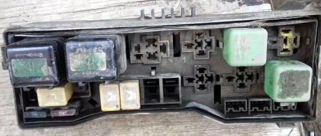
Relay and fuse box
It is located on the left side at the rear of the cab or behind the left mudguard. High power fuses or fuses and separate relays will be located there.
Photo example
Diagram
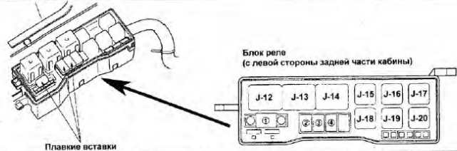
See the table below for the relay assignment.
Relay box
Diagram

Individual elements can be located outside the blocks. For example B -261.
Decoding
| B 9 | Relay for system changing the interval of work of the wipers (INTERMITTENT) |
| B-19 | Charging relay |
| B-19 | (CHARGE) |
| B 20 | Headlight relay |
| B 20 | (HEAD) |
| B 21 | Relay for air conditioning, heating and ventilation (HEATER & AIR CON.) |
| B-22 | Dimension relay (TAIL) |
| B-23 | Combination switch relay |
| B-23 | (DIMMER) |
| B-24 | Horn relay |
| B-24 | (HORN) |
| B-34 | Rear fog lamp relay |
| B-34 | (REAR FOG) |
| B-35 | Turning light relay |
| B-35 | (CORNERING LIGHT) |
| B-35 | Rear fog lamp relay |
| B-35 | (RR FOG) |
| B-36 | Power window relay |
| B-36 | (POWER WINDOW) |
| B-37 | Pressure switch relay |
| B-37 | (A / C THERMO) |
| B-38 | Mountain brake relay |
| B-38 | (EXH. BRAKE) |
| J-12 | Starter relay |
| J-12 | (STARTER) |
| J-13 | Glow plug relay |
| J-14 | Glow plug relay |
| J-16 | Capacitor Warm-up Control (CDS) Relay |
| J-18 | Exhaust brake control relay |
| J-18 | (EXH. BRAKE CONTROL) |
| J-19 | 4WD system relay |
| J-19 | Air conditioner shutdown relay |
| J-19 | (A / C CUT). |
| J-20 | Turn signal repeater relay (MARKER LIGHT) |
Type 2
This type of fuse boxes is used in the 6th generation and for cars with 4HG1-1, 4JJ1, 4HK1 engines.
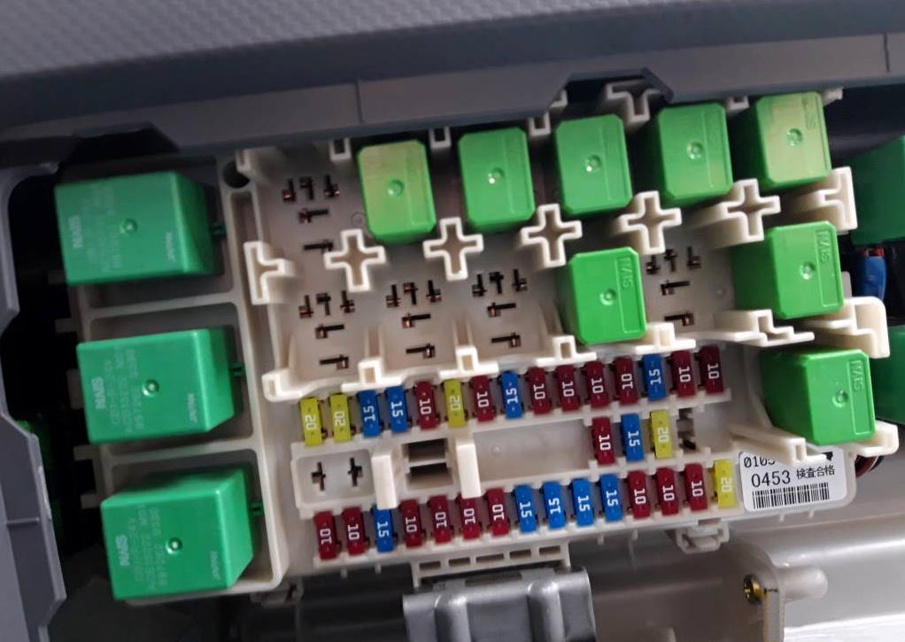
Box inside the car
The main box with fuses and relays is also located in the cabin in the instrument panel, on the passenger side.

Photo
Diagram

Assignment
| 1 | 20A Power take-off (battery) |
| 2 | 20A Rear right window regulator |
| 3 | 15A Interior lighting, audio system |
| 4 | 15A Door locks |
| 5 | 10A Fog lights |
| 6 | 20A Power windows |
| 7 | 10A Anti-lock braking system (ABS) |
| 8 | 15A Wiper |
| 9 | 10A Low beam (left headlight) |
| 10 | 10A Engine management system (battery) |
| 11 | 10A Low beam (right headlight) |
| 12 | 10A Brake lights |
| 13 | 15A Ignition (IGN2) |
| 14 | 10A High beam (left headlight) |
| 15 | 10A High beam (right headlight) |
| 16 | 10A Power take-off (KEY ST) |
| 17 | 10A Starter |
| 18 | 15A Ignition (IGN1) |
| 19 | 10A Airbags |
| 20 | 10A Engine control module (ECM) |
| 21 | 10A Instruments |
| 22 | 10A Lights (batteries) |
| 23 | 15A Audio system (ACC) |
| 24 | 15A Exterior mirror drive |
| 25 | 15A Horn |
| 26 | 15A Direction indicators, hazard warning lights |
| 27 | 10A Marker lights |
| 28 | 10A Backlight |
| 29 | 10A Side cornering lights, rear fog light |
| 30 | 20A Heater fan motor, 10A air conditioner |
| 31 | 20A Cigarette lighter |
| 32 | Spare |
| 33 | Spare |
| Relay | |
| 1 | Stop lights |
| 2 | Heater fan motor |
| 3 | Ignition lock (KEY ON) |
| 4 | 4JJ1, 4HK1: Door locks (locking) |
| 4HG1: Reserve seat | |
| 5 | 4JJ1, 4HK1: Rear fog light |
| 4HG1: Reserve seat | |
| 6 | Basic wiper mode |
| 7 | Sound signal |
| 8 | Wiper modes (HIGH/LOW) |
| 9 | Fog lights |
| 10 | Power take-off (MAIN) |
| 11 | 4JJ1, 4HK1: Door locks (opening) |
| 4HG1: Reserve seat | |
| 12 | Power windows |
| 13 | Headlights (low beam) |
| 14 | 4JJ1, 4HK11), 4HG1: All wheel drive |
| 4HK12): Engine brake control (models with ABS) | |
| 15 | Headlights (high beam) |
| 16 | Marker lights |
| 17 | 4JJ1, 4HK11): Power take-off solenoid valve (models with manual transmission) |
| 4HK12): Spare seat | |
| 4HG1: Engine brake release | |
| 18 | 4JJ1, 4HK11): Power take-off disengagement |
| 4HK12): Spare seat | |
| 4HG1: Engine brake | |
| 19 | 4JJ1, 4HK11): Charging (with engine running) |
| 4JJ1, 4HK11), 4HG1: Transfer Case (Ignition 1) | |
| 4HK12): Power take-off solenoid valve (models with manual transmission) | |
| 20 | 4JJ1, 4HK11): Power windows (rear) |
| 4HK12): Power take-off disengagement | |
| 4HG1: Charging (with engine running) | |
| 21 | 4HG1: PTO solenoid valve (models with manual transmission) |
| 22 | 4HG1: Disabling the power take-off |
- 1) Cars with 4JJ1/4HK1 engine (models with hydraulic brake system)
- 2) Cars with 4HK1 engine (models with air brake system)
The fuse number 31 at 20A is responsible for the operation of the cigarette lighter.
Box behind the cabin
Another box with fuses and relays is located outside the car. To access, remove the protective cover.

Photo example

Diagram
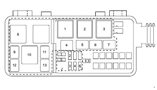
Allocation
| 1 | 10A Marker lamps |
| 4HG1: Not used | |
| 1 | 15A 4JB1-TC: Fuel heater |
| 2 | 10A Engine Control Module (ECM) |
| 4JB1-TC, 4HG1: Not used | |
| 3 | 10A Battery |
| 3 | 15A 4JB1-TC: Battery |
| 4 | 10A Conditioner |
| 4JB1-TC: Not used | |
| 5 | 20A 4HK13): Air conditioner, ABS |
| 4HK11,2), 4JJ1: Not used | |
| 4JB1-TC: Marker lights | |
| 4HG1: Fuel heater | |
| 6 | 15A 4JB1-TC: Air conditioner |
| 4HK1, 4JJ1: Not used | |
| 4HG1: Engine stop | |
| Realy | |
| 1 | Starter |
| 2 | 4HK1, 4JJ1: Engine Control Module (ECM) |
| 4JB1-TC, 4HG1: Not used | |
| 3 | Glow plugs |
| 4 | Air conditioning compressor |
| 5 | Condenser fan |
| 6 | 4HK1, 4JJ1: Starter Disable |
| 4JB1-TC: Engine brake | |
| 4HG1: Engine stop | |
| 7 | 4HK11), 4JJ1: Marker lamps (models with rear fog lamps) |
| 4HK12,3): Engine brake | |
| 4JB1-TC, 4HG1: Fuel heater | |
| 8 | Gear selector |
| 9 | 4WD 4WD (NPS Model) |
| 10 | Fuel heater (models with fuel heater) |
| 11 | Transfer case control (NPS model) |
| 12 | Starting the Engine (Models with Fuel Heater) |
| 13 | 4HK12,3): Marker lamps (models with rear fog lamps) |
- 1) Models with 4HK1 engine (Euro 4 emission standards) and hydraulic brake system, models with 4JJ1 engine
- 2) Models with 4HK1 engine (Euro 2 or Euro 3 emission standards) with hydraulic brake system
- 3) Models with 4HK1 engine and air brake system
- 4) Models with 4JB1-TC engine (type 1)
- 5) Models with 4HG1 engine (type 1)
Type 3
Suitable for 4JB1 engines. The location of the boxes is the same as Type 2.
Box inside the car
Photo

Diagram

Appointment
| 1 | 10A Lamps (batteries) |
| 2 | 10A Interior lighting, audio system |
| 3 | 10A Engine brake |
| 4 | 15A Door locks |
| 5 | 15A Fog lights |
| 6 | 25A Power windows |
| 7 | 10A High beam (left headlight) |
| 8 | 10A High beam (right headlight) |
| 9 | 10A Brake lights |
| 10 | 10A Low beam (left headlight) |
| 11 | 10A Low beam (right headlight) |
| 12 | 10A Marker lights |
| 13 | 10A Lamps (batteries) |
| 14 | 10A Ignition (IGN2) |
| 15 | 10A Starter |
| 16 | 10A Engine stop |
| 17 | 10A Ignition (IGN1) |
| 18 | 10A Reversing lights |
| 19 | 10A Instruments |
| 20 | 15A Audio system (ACC) |
| 21 | 10A Air conditioner |
| 22 | 15A Horn |
| 23 | 15A Direction indicators, hazard warning lights |
| 24 | 25A Wiper |
| 25 | Spare |
| 26 | Spare |
| 27 | Spare |
| Relay | |
| 1 | Marker lights |
| 2 | Headlights (high beam) |
| 3 | Headlights (low beam) |
| 4 | Power windows |
| 5 | Stop lights |
| 6 | Charging (when the engine is running) |
| 7 | Ignition lock (KEY ON) |
| 8 | Engine brake |
| 9 | Basic wiper mode |
| 10 | Wiper modes (HIGH/LOW) |
| 11 | Fog lights |
| 12 | Sound signal |
| 13 | Reserve place |
| 14 | Fan motor |
Box behind the cabin
Photo example

Diagram

Assignment
| 1 | 10A 4HG1 (type 2), 4HG1-T: Engine stop |
| 1 | 15A 4JB1-TC (type 2), 4JB1: Power supply |
| 2 | 10A 4HG1 (type 2), 4HG1-T: Spare battery |
| 2 | 15A 4JB1-TC (type 2), 4JB1: Fuel heater |
| 3 | 10A 4HG1 (type 2), 4HG1-T: Fuel heater |
| 3 | 20A 4JB1-TC (type 2), 4JB1: Air conditioner |
| 4 | 10A 4HG1 (type 2), 4HG1-T: Air conditioner |
| 4 | 20A 4JB1-TC (type 2), 4JB1: Condenser fan |
| Relay | |
| 1 | Preheating |
| 2 | Starter |
| 3 | 4HG1 (type 2), 4HG1-T: Engine stop |
| 4JB1-TC (type 2), 4JB1: Not used | |
| 4 | Fuel heating |
| 5 | Condenser fan |
| 6 | Engine brake |
| 7 | 4JB1-TC (type 2), 4JB1:CSD |
| 4HG1 (type 2), 4HG1-T: Not used | |
That’s all. And if you have something to add or want to share your diagrams – write in the comments.
Hello please is there a pdf for this Isuzu N Series Views and Relay (Elf)
Any luck for Isuzu Elf NKR817052297 fuse and relay diagrams?
For the 4hk1 external fuse box,,,what are the 30 to 60amp fuses for?
Isuzu Elf 4JJ1 electrical fault at reversing light and buzzer circuit. Please anyone have a suggestion where to look for …??? All looks good but the Reversing ( Backup ) lights and buzzer do not work. The reversing was checked and appears O.K. Need to find the electrical diagram of that circuit. Please any Help
where is the fuse or relay located that controls the battery driven vacuum pump that starts when ignition is turned on, 2018 Isuzu Npr with gas engine
Sir plz share issuzu NPS NPR FTS FTR FUSE relay diagram
Where is the fuse that controls power to the odb2 port?
Me dejó de funcionar la cigarrera para meter un cargador de chupón ..no funciona
Trying to find fuse location for dash lights, temp and fuel gage truck follow the type 1 diagram
vehicle is 2000 chev w5000. I have found fuses not listed hidden behinds dash board but can not locate these. nothing seems to mention them
Having problem my Isuzu 4hf1 battery sparks during connection the terminal to the post..
Hi.
This page is very helpful
i need fuse and relay diagram, Izuzu N3, yr model 2006, Body type: Tuck Cargo Truxk with crane, Series: Lowsteelsidings