Gazelle Next is a family of Russian small-tonnage cars and minibuses produced in 2013, 2014, 2015, 2016, 2017, 2018, 2019, 2020, 2021 and up to the present. Also known as Ceylan Sonraki. In this publication you will find a description of the Gazelle Next fuses and relays with box diagrams and their locations. Note the fuse responsible for the cigarette lighter. In conclusion, you can familiarize yourself with the full instruction manual for Gazelle Next.

Contents
Passenger compartment
It is located in the passenger compartment under a panel, behind a protective cover, on the back of which the current scheme can be applied.

This fuse and relay box also contains a diagnostic connector.
Diagram
Designation
| F1 | 20A Windscreen wiper, glass washer |
| F2 | 10A Lighting control module, instrument lighting. |
| F3 | 5A Power mirrors |
| F4 | 25A Glass lifters |
| F5 | 10A Heated mirrors |
| F6 | 10A Heated driver’s seat |
| F7 | 15A Additional heater |
| F8 | Reserve |
| F9 | 10A Locking differential |
| F10 | 15 / 20A Socket for second row of seats, horns (platform vehicle with petrol engine), Horns (solid metal vehicle) 10A Power door, door lamp (bus) |
| F11 | Reserve |
| F12 | Socket, radio (car with an all-metal body) |
| F13 | 7.5A Daytime running lights |
| F14 | 5A Rear fog lights |
| F15 | 7,5 / 10А Direction indicators |
| F16 | 7.5A Instrument cluster, speed sensor, heater control |
| F17 | 5A Engine management system (vehicle with diesel engine) |
| F17 | 15A Engine management system (a car with a gasoline engine) |
| F18 | 5A Anti lock ABS brakes |
| F19 | 20A Cigarette lighter sockets |
| F20 | Hazard warning lights (platform car, bus) |
| F20 | Central locking, radio (car with an all-metal body) |
| F21 | Lighting control module, backlight |
| F22 | Interior lighting |
| F23 | Central locking, radio (platform car) |
| F23 | Radio, loud-speaking device (bus) |
| F23 | Hazard warning lights (solid metal vehicle) |
| F24 | Instrument cluster, diagnostic block, pre-heater control panel, tachograph |
A 19 20A fuse is responsible for the operation of the cigarette lighter and additional sockets.
Complete relay circuit

Relay
| К1 | Wiper relay |
| K2 | Heater relay |
| K3 | Ignition switch unload relay |
| K4 | Footrest light relay (solid -body vehicle with two-row cab) Light board relay (bus) |
| K5 | Heater relay (diesel vehicle) |
| К6 | Differential lock relay |
| K7 | Horn Relay (Except Platform Vehicles and Diesel) |
| К8 | Lock unload relay (solid metal vehicle) |
The turn switch relay is located on the switch itself. To access it, you need to remove the steering wheel and disassemble the steering column switch.

Engine compartment
Relay and fuse box
Located on the left side, in the back.

Diagram

Appointment
| F1 | 15A Fog lamp relay |
| F2 | 10A Brake signals |
| F3 | 20A Horn relay (bus) |
| F4 | 25A Fuel heater relay (diesel vehicle) 20A Main relay (gasoline vehicle) |
| F5 | 25A Coolant heater (vehicle with diesel engine) 5A Engine control unit (vehicle with gasoline engine) |
| F6 | 15A Fuel pump (car with a gasoline engine) 25A Starter and instrument switch (bus) |
| F7 | 25A Anti lock ABS brakes |
| F8 | 25A Air conditioner fan 20A Independent heater (bus) |
| F9 | 10A Low beam (left headlight) |
| F10 | 10A Low beam (right headlight) |
| F11 | 10A High beam (left headlight) |
| F12 | 10A High beam (right headlight) |
| F13 | 10A Side lights (port side) |
| F14 | 10A Side lights (starboard) |
| F15 | 10A Reverse light |
| F16 | 10A A / C Compressor |
| F17 | 40A Heater |
| F18 | 40A Anti-lock braking system ABS |
| F19 | 40A Instrument and starter switch (ignition) |
| Relay | |
| К1 | A / C compressor relay |
| K2 | Starter lock relay (diesel vehicle) Fan clutch relay (gasoline vehicle) |
| K3 | Fuel pump relay (petrol engine) |
| K4 | Fog lamp relay |
| K5 | Headlamp high beam relay |
| К6 | Headlamp low beam relay |
| K7 | Air conditioner fan relay |
| К8 | Wiper Stowage Relay |
| K9 | Fuel Heater Relay (Diesel Vehicle) |
| K9 | Main relay (gasoline engine vehicle) |
| K10 | Starter relay |
Fuse box
It is located under the hood, on the right side of the bulkhead, and consists of fusible links.
Diesel models
Diagram
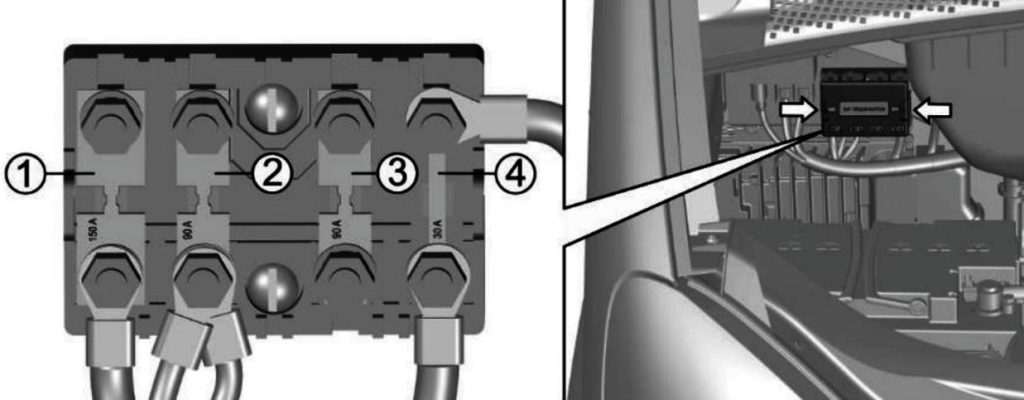
Functions
| 1 | 125A Prestarting air heater |
| 2 | 90A Common positive circuit of the vehicle |
| 3 | 40A Reserve |
| 4 | 30A Engine management system |
Gasoline models
Photo for example

Assignment
- 90A Common positive circuit of the vehicle
- 60A Reserve
Gazelle Next instruction
More information about repair and maintenance, as well as use (for example, a radio tape recorder) in Gazelle Next, you can find out by studying this material: ” download “.
And if you have any questions, ask them in the comments.