The 3rd generation Mercedes-Benz Sprinter with body markings 907 and 910 was produced in 2018, 2019, 2020, 2021, 2022, 2023. In this material you can find a description of the fuses and relays Mercedes Sprinter 907 910 with box diagrams and photo examples of their location. Select the cigarette lighter fuse.
The execution of the boxes and the purpose of the elements in them may differ from those presented and depend on the year of manufacture, the level of equipment and the region where your car was delivered.
Not suitable generation or diagram?
[Description of Sprinter 1G]
[Description of Sprinter 2G]
Contents
Fuse box and relay under the panel
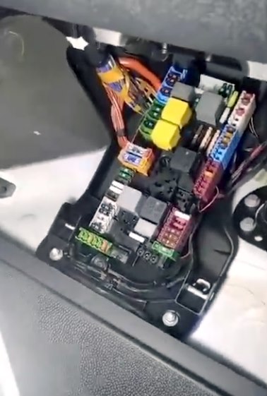
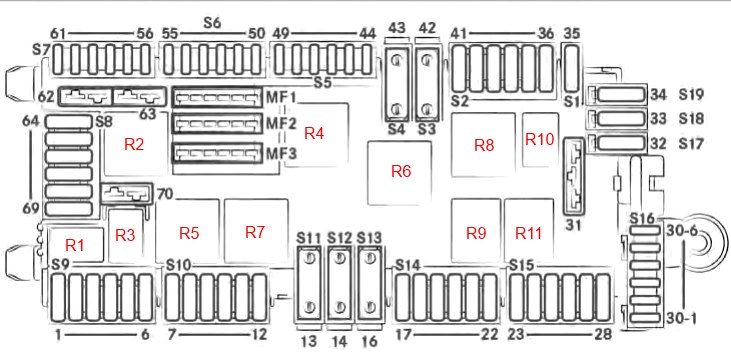
Under the instrument panel, in the front passenger footwell, there is a main fuse and relay box.
Diagram
Assignment
Fuses
| MF1 | |
| 15-1 | 5A Engine control unit; |
| Common Transmission Module (CPC); | |
| ESP module; | |
| All-wheel drive module; | |
| Moderator; | |
| Air suspension. | |
| MF2 | |
| 15-2 | 5A Feedback cable, terminal 15 relay; |
| Headlight range adjustment, halogen headlight; | |
| TCO tachograph; | |
| Radar sensor for active brake booster; | |
| Switching off the reversing signaling device, power take-off, adjustment of the working speed; | |
| Connection to a DIN socket. | |
| MF3 | |
| 30-Т | 7.5A Multifunction camera; |
| TCO tachograph; | |
| DIN socket connection, roof; | |
| Terminal 15, undervoltage relay; | |
| Instrument panel; | |
| Central oil pump. | |
| S9 | |
| 1 | Not assigned |
| 2 | 10A Common Transmission Module (CPC) |
| 3 | 10A Engine control unit OM642 / OM651 / M274 |
| 4 | 7.5A DIN connector, cab |
| 5 | 10A Common Transmission Module (CPC) |
| 6 | 5A Radiator fan (not for OM654) |
| S10 | |
| 7 | 30A Automatic transmission |
| 8 | 30A Body Controller |
| 9 | 30A Body Controller |
| 10 | 30A Heating, SCR catalyst. |
| 11 | 10A Ceiling control module (standard); |
| 10A Ceiling control module, cab chassis; | |
| 15A Ceiling control module, high. | |
| 12 | 15A Pump, SCR catalyst |
| S11 | |
| 13 | 60A Automatic transmission NAT3 |
| S12 | |
| 14 | 25/40A ESP valves (Premium), vehicles with electromechanical parking brake; |
| ESP valves (Standard). | |
| S13 | |
| 16 | 60A ESP pump |
| S14 | |
| 17 | 30A Controller |
| 18 | 30A Body Controller |
| 19 | 10A Terminal block for bodybuilder electrical connection |
| 20 | 25A Front passenger door control unit |
| 21 | 25A Driver door controller |
| 22 | 10A Air suspension control unit (LFA) |
| S15 | |
| 23 | 25A Fan control unit |
| 24 | 7.5A USB socket (cockpit, glove box); |
| Converter socket 115/230 V. | |
| 25 | 15A Cigarette lighter, center console |
| 26 | 15A Information panel socket |
| 27 | 25A Converter socket, 115V / 230V. |
| 28 | 7.5A Radio preset; |
| Service lift; | |
| Voltage converter antenna; | |
| Converter socket, 115 V / 230 V for vehicles with external battery. | |
| S16 | |
| 30-1 | Not assigned |
| 30-2 | Not assigned |
| 30-3 | 5A Central locking |
| 30-4 | 5A Alarm (ATA) |
| 30-5 | Not assigned |
| 30-6 | 10A Electronic ignition lock control unit |
| 31 | 25A Start relay contact 15-II |
| S17 | |
| 32 | Not assigned |
| S18 | |
| 33 | 5A Voltage quality sensor (SEB) |
| S19 | |
| 34 | 10A Interior lighting electronics |
| S1 | |
| 35 | 7.5A Advance Caravanning (ACU) – Motorhome |
| S2 | |
| 36 | 5A Air conditioning control panel |
| 37 | 5A Electric steering lock (ESTL) |
| 38 | 10A Steering column (SCSM) |
| 39 | 10A Antenna; |
| Navigation; | |
| Two way radio. | |
| 40 | 5A Flashing beacon |
| 41 | 25A Radio multimedia system (C5 / NTG6), radio preset |
| S3 | |
| 42 | Not assigned |
| S4 | |
| 43 | Not assigned |
| S5 | |
| 44 | 5A Multimedia control panel |
| 45 | 5A Charger bracket; |
| Wireless Mobile Interface (WMI). | |
| 46 | 7.5A Multimedia connection box (MMI) |
| 47 | 5A Hermes (UMTS/LTE communication module) |
| 48 | 5A Stationary heating Telestar |
| 49 | 5A Center display |
| S6 | |
| 50 | 5A Auxiliary headlight, left (platform bodybuilder) |
| 51 | 5A Auxiliary headlight, right (platform bodybuilder) |
| 52 | 7.5A Airbag control unit |
| 53 | 5A Diagnostics |
| 54 | 5A Relay power supply |
| 55 | 7.5A TS engine (Diesel), engine control unit (OM651) |
| S7 | |
| 57 | 10A Soot particle sensor; |
| NOx sensor; | |
| Soot particle sensor (not for OM654) | |
| 58 | 10A Engine, exhaust gas recirculation (EGR) (OM642 / OM651); |
| Engine (not for OM654). | |
| 59 | 15A NOx sensor before and after catalytic converter (not OM654) |
| 60 | 10A Lambda probe |
| 61 | 7.5A Motor M274; Motor (OM642 / OM651). |
| H2 | |
| 62 | 15A Engine control unit (not for OM654) |
| 63 | 20/25A Engine control unit; Engine (M274); |
| Engine (not for OM654). | |
| S8 | |
| 64 | 30A Body controller |
| 65 | 30A Body controller |
| 66 | 15A Roof fan |
| 67 | 25A Fuel metering control unit (FSCM) |
| 68 | 15A Right LED headlight |
| 69 | 15A Left LED headlight |
| H2 | |
| 70 | 30A Wipers |
Fuses with numbers 24, 25, 26, 27, as well as additional elements in the driver’s seat block, are responsible for the operation of the USB port and the cigarette lighter.
Relay
| R1 | 30A Reserve |
| R2 | 50A Terminal 87 motor |
| R3 | 30A Terminal 87 common drive module (CPC) |
| R4 | 40A Terminal 15-1 |
| R5 | 40A Turns the wipers on and off. |
| R6 | 40A Reserve |
| R7 | 40A Speed wipers |
| R8 | 40A Terminal 50 starter |
| R9 | 50A Terminal 15R (vehicles without auxiliary battery) |
| R10 | 30A Terminal 15-2 |
| R11 | 50A Terminal 15R (vehicles without auxiliary battery) |
Fuse and relay boxes under the driver’s seat
Boxes with fuses and relays can be installed under the driver’s seat, as well as the passenger’s seat.

Fuse box
To access the unit, you need to remove the protective cover from the side of the driver’s seat.
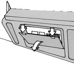
Photo – example

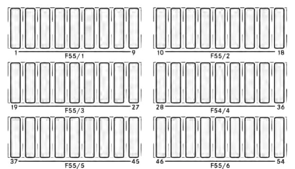
Diagram
Designation
| F55 / 1 | |
| 1 | 10A Additional turn signal lamp |
| 2 | 15A Rear window wiper, right |
| 3 | 30A All wheel drive |
| 4 | 25A Terminal block for electrical connection |
| 5 | 25A Driver’s seat adjustment unit |
| 6 | 10A Driver’s seat heater |
| 7 | 25A Driver’s lumbar support |
| 8 | 5A Tire pressure monitoring |
| 9 | 5A Parking assistant; Main camera (RVC). |
| F55 / 2 | |
| 10 | 25A Trailer hitch right (trailer socket) |
| 11 | 15A Control unit with socket for trailer |
| 12 | 25A Hitch left (trailer socket) |
| 13 | 15A Control unit with socket for trailer |
| 14 | 25A Multi Function Module (MPM) |
| 15 | 25A Multi Function Module (MPM) |
| 16 | 25A Rear chamber blower |
| 17 | 20A Additional heating (water heating) |
| 18 | 15A Automatic transmission, additional oil pump |
| F55 / 3 | |
| 19 | 15A Parking heating; |
| Terminal 15 on the auxiliary battery. | |
| 20 | 5A Auxiliary battery voltage measurement |
| 21 | 15A Heated rear window, left |
| 22 | 15A Heated rear window right |
| 23 | 7.5A Tail lift / tipper (before installation) |
| 24 | 15A Terminal block for electrical connection |
| 25 | 5A Roof fan relay |
| 26 | 7,5A Signal special, cab bodybuilder |
| 27 | 30A Heated rear window |
| F55 / 4 | |
| 28 | 15/30A Sliding door on the left; |
| Electric sliding door on the left. | |
| 29 | 15/30A Sliding door right; |
| Electric sliding door right. | |
| 30 | 5A Antenna switch box |
| 31 | 7.5A Automatic transmission |
| 32 | 10A Automatic transmission |
| 33 | 30A Brake booster |
| 34 | 15/30A Siren relay; Preparing for a motorhome. |
| 35 | 15/30A Flashing beacon with siren; |
| 30A Preparing for a motorhome. | |
| 36 | 30A Preparing for a motorhome |
| F55 / 5 | |
| 37 | 10A Electric step left |
| 38 | 10A Electric footrest right |
| 39 | 5A Warning buzzer; |
| Electric step, right and left. | |
| 40 | 10A Automatic transmission (NAT2) |
| 41 | 5A Terminal 15 special signal |
| 42 | 5A Rear view camera (RVC); |
| Interior mirror with rear view monitor. | |
| 43 | 15A Power socket, cab |
| 44 | 15A Power socket, D-pillar, left |
| 45 | 15A Power socket, D-pillar, right |
| F55 / 6 | |
| 51 | 5/7.5A USB port, left |
| 52 | 5/7.5A USB port, right |
Relay box
Installed under the driver’s seat.
Diagram

Appointment
| 1 | Heated windshield |
| 2 | Terminal 15 |
| 3 | Rear window heating |
| 4 | Sockets, rear |
| 5 | Interior lighting |
| 6 | Not used |
| 7 | Not used |
| 8 | Not used |
| 9 | Not used |
| 10 | Not used |
| 11 | Not used |
| 12 | Not used |
| 13 | Not used |
| 14 | Not used |
| — | mini relay |
| 15 | Right rear wiper |
| 16 | Manufacturer Terminal Block Housing |
| 17 | Switch, reverse signal |
| 18 | Roof fan |
| 19 | Additional oil pump |
| 20 | Electric footboard right 1 |
| 21 | Electric footboard right 2 |
| 22 | Electric step left 1 |
| 23 | Electric step left 2 |
| 24 | Siren |
| 25 | Flashing beacon with siren |
| 26 | loading lift |
Battery fuse box
On the positive terminal of the battery there is a block of power fuses made in the form of a fusible insert.
Diagram

Decoding
| F150 / 1 (MFB-1) | |
| 1 | Battery sensor |
| 2 | Not assigned |
| 3 | Main fuse box (MFB-2) |
| 4 | 50A Energy Distribution Center Terminal 30 (F30-1 – F30-6) |
| 5 | 125A Additional PTC heater |
| F150 / 4 (MFB-2) | |
| 1 | 125A Terminal 30T, fuse box, driver’s seat base (F55/1-F55/6) |
| 2 | 125A Electric control |
| 3 | 300A Generator |
| 4 | 400A Generator |
| 5 | 175A Power Distribution Center (PDC), FB-P |
| 6 | 80A Glow output stage (GZE) |
| 7 | 40/70/80A Radiator fan (not for OM654); |
| Engine radiator fan; | |
| Radiator fan (not for OM654). | |
| 8 | 100A Motorhome main fuses |
| 9 | Not assigned |
| 10 | 25/50/100A Rear air conditioner |
| 11 | 100/150A Auxiliary Battery / Battery Disable Relay; |
| Retarder without additional battery. | |
| 12 | 40A Air Suspension (LFA) |
| 13 | 80A Heated windshield |
| F150 / 5 (MFB-ZB) | |
| 1 | 100A Retarder |
| 2 | 250A Tail lift / tipper (preparation) |
| 3 | additional battery |
| 4 | 150A Battery Disconnect Relay |
| 5 | 60A Socket, converter |
| 6 | 25A Additional heating |
| F59 / 1 & F59 / 2 | |
| 1 | 40A Heated windshield |
| 2 | 40A Heated windshield, right |
If you need information about fuses and relays in a pdf file, you can download it here.
We also posted a video on our YouTube channel. Look and subscribe.
And if you know how to make the material better – write in the comments.
which non critical fuse can i tap that is not
constantly on (or have power)? I want to tap a light switch controller. (Auxbeam light switch controller)
I bought a car cam and has a feature to go on if when park the vehicle shakes but needs to be attached to power on I have it connected to the cig outlet on top of the dash – 2019 Sprinter. It is on only when the car is on – same with all the other usb ports.
Can’t find tail light fuse port
Hi, in the battery compartment there is a fuse block f150/1. The fuses in the block are good via continuity check.
There is a relay encased in the fuse block I suspect is bad. I would like to either test the relay or back probe and test the 4 wires controlling the relay. But I don’t know which wires close the relay?
My sprinter will not start despite 12.6 v at the battery terminals unless I jump the positive terminal to the smaller terminal on the fuse block. The fuse block part number is A9075407060
And the encased relay part number is 754H R1A B010. Wire colors to the relay are brown, white/red, green/purple, red/black. Thank you.
Hi Terry, have you solved this problem, I have exact the same on a Sprinter from 2019.
Hello, can you please tell me the location or fuse number of the DRL for 2024 Sprinter? I don’t see anything labeled as “Daytime Running Lights” from the diagram and/or assignment. My DRL is not very bright like other Sprinters. Thank you.
Where can I find fuse for Mass airflow sensor for 2023 Mercedes Sprinter 2500 Diesel?
Thank you