Mercedes W251 R-Class was produced in 2005, 2006, 2007, 2008, 2009, 2010, 2011, 2012 and 2013 in various R280, R300, R320, R350, R500, R550, R63 AMG versions. During this period, the model has been restyled. In this publication, we will present a description of the fuses and relays Mercedes w251 with box diagrams and their locations. Note the fuse responsible for the cigarette lighter.

The purpose of the fuses and relays may differ from the one shown and depends on the year of manufacture and the region where your car was delivered.
Contents
Passenger compartment
Fuse box
On the right side of the dashboard, behind a protective cover, there is a fuse box.

Photo for example

Diagram

Assignment
- 10 – 10A Electronic auxiliary fan controller
- 11 – 5A Instrument cluster
- 12 – 15A KLA system control panel (Automatic climate control system)
- 13 – 5A Upper control panel control unit / Steering column module
- 14 – 7.5A EZS control unit, CD changer (up to 2008 model year)
- 15 – 5A Electronic compass / multimedia interface control unit (from model year 2009)
- 16 – Reserve
- 17 – Reserve
- 18 – Reserve
Power fuse box
This unit is located next to the battery under the front passenger seat.

Photo

Diagram

Designation
| 78 | 150A Diesel engines: Additional electric heater |
| 79 | 60A SAM control unit, rear |
| 80 | 60A SAM control unit, rear |
| 81 | 40A Engines 642.870: AdBlue® power supply relay |
| Engines 276: Fuse and relay box in the engine compartment | |
| 82 | 150A Before MY 2008: Fuse and relay box in cargo area |
| 100A From model year 2009: Fuse and relay box in the cargo area | |
| 83 | 5A Passenger weight system (WSS) control unit (USA) |
| 84 | 10A Restraint control unit |
| 85 | 25A From model year 2009: DC/AC transformer control unit (115V socket) |
| 86 | 30A Front panel fuse box |
| 87 | Reserve |
| 88 | 70A Before model year 2008: SAM control unit, front |
| 40A From model year 2009: SAM control unit, front | |
| 89 | 70A SAM control unit, front |
| 90 | 70A SAM control unit, front |
| 91 | 40A Fan regulator |
Engine compartment
Fuse and relay box
In the engine compartment, on the right side, is the main fuse and relay box.

Diagram
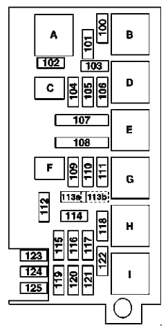
Allocation
| 100 | 30A Wiper motor |
| 101 | 15A Suction motor and air conditioning fan with integrated regulator |
| Engines 272, 273: (from model year 2009) | |
| Change-over valve in the closed ventilation system of the fuel tank | |
| Cable termination electr. circuit terminal 87 M1e | |
| Engines 113, 272: (up to MY 2008) | |
| Regeneration change-over valve | |
| 272 engines: (up to MY 2008) | |
| Noise suppression capacitor 1 audio module | |
| Noise suppression capacitor 2 audio modules | |
| Cylinder 1 ignition coil | |
| Cylinder 2 ignition coil | |
| Cylinder 3 ignition coil | |
| Cylinder 4 ignition coil | |
| Cylinder 5 ignition coil | |
| Cylinder 6 ignition coil | |
| Engines 642: | |
| CDI control unit | |
| O2 probe before catalytic converter | |
| Engines 642.870/872: | |
| O2 probe before catalytic converter | |
| 102 | 15A Engines 642, (642.870 to 31.7.10) (from model year 2009): Gearbox oil cooler circulation pump |
| 276 Engines: Charge Air Cooler Circulation Pump | |
| Engines 156: Engine oil cooler circulation pump | |
| 103 | 20A Engines 642.950, 642.870/872: CDI control unit |
| Engines 272: ME control unit | |
| Engines 276: | |
| ME control unit | |
| Plug connection engine/engine compartment | |
| 25A Engines 113: | |
| ME control unit | |
| Fuel injector 1st cylinder | |
| Fuel injector 2nd cylinder | |
| Fuel injector 3rd cylinder | |
| Fuel injector 4th cylinder | |
| Fuel injector 5th cylinder | |
| Fuel injector 6th cylinder | |
| Fuel injector 7th cylinder | |
| Fuel injector 8th cylinder | |
| 642 engines (up to model year 2008): CDI system control unit | |
| 104 | 15A Engines 272, 273 (from model year 2009): Cable termination electr. circuit terminal 87 M2e |
| Engines 272 (before MY 2008): | |
| Heating shut-off valve | |
| Changeover flap valve in the intake manifold | |
| Air pump changeover valve | |
| Three-plate thermostat valve Power steering pump pressure regulator valve | |
| Engines 642.950 (from model year 2009): Cable termination electr. terminal 87 circuits | |
| Engines 642.870/872 (from model year 2009): Cable termination electr. circuit terminals | |
| 642 engines (up to MY 2008): | |
| Hot-film air mass meter for the left cylinder bank | |
| Hot-film mass air flow meter of the right row of cylinders | |
| Inlet duct cut-off servomotor | |
| End of candle glow time | |
| Heating element in crankcase ventilation duct | |
| Power Steering Pump Pressure Control Valve | |
| Servomechanism for left exhaust gas recirculation flap | |
| Boost pressure control servo | |
| Engines 113: | |
| Left O2 sensor before catalytic converter | |
| Right O2 sensor before catalytic converter | |
| O2-Left sensor behind catalytic converter | |
| O2-Right sensor behind catalytic converter | |
| Variable intake manifold changeover valve | |
| ARF System Pressure Transmitter | |
| Air pump changeover valve | |
| 105 | 15A Engines 272, 273 (from model year 2009): |
| ME control unit | |
| Cable termination electr. circuit terminal 87 M1i | |
| Engines 272 (up to model year 2008): | |
| ME control unit | |
| hot-wire air mass meter | |
| Left intake camshaft hall sensor | |
| Right intake camshaft hall sensor | |
| Left hall sensor, left exhaust camshaft | |
| Hall sensor, right exhaust camshaft | |
| Left intake camshaft control solenoid | |
| Right intake camshaft control solenoid | |
| Left exhaust camshaft control solenoid | |
| Right intake camshaft control solenoid | |
| Fuel injector 1st cylinder | |
| Fuel injector 2nd cylinder | |
| Fuel injector 3rd cylinder | |
| Fuel injector 4th cylinder | |
| Fuel injector 5th cylinder | |
| Fuel injector 6th cylinder | |
| Engines 276: Engine/engine compartment plug connection | |
| 642 engines (up to model year 2008): CDI control unit | |
| Engines 642.950: | |
| CDI control unit | |
| Plug connection engine compartment/interior | |
| Engines 642.870/872: | |
| CDI control unit | |
| Plug connection engine compartment/interior | |
| Cable termination electr. terminal 87 circuits | |
| Engines 113: | |
| ME control unit | |
| Interference suppression capacitor 1 radio receiver | |
| Interference suppression capacitor 2 radios | |
| Ignition coil 1st cylinder | |
| Ignition coil 2nd cylinder | |
| 3rd cylinder ignition coil | |
| 4th cylinder ignition coil | |
| Ignition coil 5th cylinder | |
| Ignition coil of the 6th cylinder | |
| Ignition coil of the 7th cylinder | |
| Ignition coil of the 8th cylinder | |
| 106 | Reserve |
| 107 | 40A Engines 113, 272, 273: Electric air pump |
| 108 | 40A Air compressor motor |
| 109 | 25A ESP control unit |
| 110 | 10A Alarm Siren |
| 111 | 30A Servo drive module, automatic transmission DIRECT SELECT |
| 112 | 7,5A Front left headlight |
| Block headlight front right | |
| 113 | 15A Horn left |
| Sound signal right | |
| 114 | 5A SAM control unit, front |
| Engines 272 (up to model year 2008): ME control unit | |
| 115 | 5A ESP control unit |
| 116 | 7.5A Electrical control module (VGS) |
| 117 | 7.5A DTR control module (Distronic) |
| 118 | 5A Engines 272, 273, 276: ME control unit |
| 642 engines: CDI control unit | |
| 119 | 5A Engines 642.870/872: CDI control unit |
| 120 | 10A Engines 272, 273, 276 (from model year 2009): |
| Relay el. motor terminal 87 circuit | |
| ME control unit | |
| Engines 113, 272 (up to model year 2008): ME control unit | |
| Engines 642 (since 2009 model year): Relay el. motor terminal 87 circuit | |
| 642 engines (up to model year 2008): CDI system control unit | |
| 121 | 20A Heater STH (auxiliary heating system) |
| 122 | 25A Engines 272, 273, 276, 642: Starter |
| 123 | 20A Engines 642: Fuel filter condensation sensor with heating element |
| Diesel engines from 1.9.08: Fuel filter condensation sensor with heating element | |
| 124 | 7.5A Electro-hydraulic power steering |
| 125 | Reserve |
| Relay | |
| А | Wiper Mode Relay 1/2 |
| B | Relay on/off wiper |
| C | Engines 156: Coolant circulation pump relay |
| 642 engines (from model year 2009): Coolant circulation pump relay | |
| 642 engines (up to model year 2008): Additional circulation pump for gearbox oil cooling | |
| D | Relay, electr. motor terminal 87 circuit |
| E | Engines 272, 273 (since MY 2009): Air pump relay |
| Before MY 2008: Catalyst Purge Air Pump | |
| F | Horn relay |
| G | Air Suspension Compressor Relay |
| H | Relay, electr. terminal 15 circuits |
| I | Starter relay |
For the front cigarette lighter, fuse number 46 at 15A is responsible.
Power fuse box
This box is located on the right side of the engine compartment.

Diagram

Appointment
- 4 – Reserve
- 5 – 40A Valid from 1.7.09: ESP control unit
- 6 – 40A Electro-hydraulic power steering, Valid until 6/30/09: ESP control unit
- 7 – 100A Suction fan for engine and air conditioner with integrated regulator
- 8 – 100A Fuse and relay box in the engine compartment
Luggage compartment
The main unit with fuses and relays is located under the boot floor, behind the soundproof lining.

Diagram
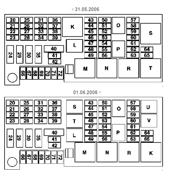
Decoding
| 20 | 5A Radio Antenna Noise Filter |
| Mic group control box (Japan; before MY 2008) | |
| Voice Control System (SBS) control unit (USA; before MY 2008) | |
| 21 | 5A HBF control unit |
| 22 | PTS control unit (parktronic) |
| Remote control receiver STH (from model year 2009) | |
| 23 | 10A DVD player |
| COMAND control and display unit (from model year 2009) | |
| Radiotelephone network compensator E (from model year 2009) | |
| Antenna compensator GSM 1800 (up to model year 2008) | |
| Rear audio control unit (before model year 2008) | |
| Control Unit (Universal Mobile Phone Interface) (Japan; before MY 2008) | |
| Electrical connector mobile phone chains (Japan; before MY 2008) | |
| 24 | 40A Front right seat belt reversible pretensioner |
| 25 | 20A From model year 2009: |
| Radio | |
| Radio receiver and navigation computer | |
| Block-panel for control and indication COMAND | |
| 15A Before MY 2008: | |
| Control panel with COMAND system display | |
| Audio system | |
| Audio module and navigation unit | |
| 26 | 25A Front right door control unit |
| 27 | 30A Front seat adjustment control unit with memory function, front passenger seat |
| Comfort Relay, Passenger Seat Adjustment (up to MY 2008) | |
| 28 | 30A Front seat adjustment control unit with memory function, driver’s seat |
| Driver’s seat comfort relay (before 2008) | |
| 29 | 40A Front left seat belt reversible pretensioner |
| 30 | 40A Fuel pump control unit |
| Engines 156: | |
| Left fuel pump control unit | |
| Right fuel pump control unit | |
| 31 | 10A Control unit for heating, seat ventilation and steering wheel heating |
| 32 | 15A AIRMATIC control unit with ADS system |
| Control unit for body level control on the rear axle | |
| 33 | 25A KEYLESS-GO system control unit |
| 34 | 25A Front left door control unit |
| 35 | 30A Speaker Amplifier |
| Subwoofer amplifier (since MY 2009) | |
| 36 | 10A Emergency call system control unit (from model year 2009) |
| Detachable power supply VICS+ETC connection (Japan; before MY 2008) | |
| 5A Emergency call system control unit (before model year 2008) | |
| 37 | 5A Rear view camera power supply module |
| Rear view camera control unit | |
| 38 | 10A Digital TV Tuner |
| Combo TV tuner (analogue/digital) (Japan) | |
| Audio interface control unit (Japan; before MY 2008) | |
| 39 | 7.5A High definition tuner control unit (from model year 2009) |
| Digital audio broadcasting control unit (as of model year 2009) | |
| RDK control unit (tire pressure monitoring system) | |
| Interface for connecting an external navigation module (South Korea; from model year 2009) | |
| SDAR control unit (US; before MY 2008) | |
| 40 | 40A Before MY 2008: Tailgate close actuator control unit |
| 30A From model year 2009: Tailgate close actuator control unit | |
| 41 | 25A Roof control panel control unit |
| 42 | 25A Roof control panel control unit |
| 43 | 20A Engines 272, 273, 276: Fuel pump control unit (from model year 2009) |
| Engines 642.872: Right fuel pump control unit (from model year 2009) | |
| Until 05/31/2006: | |
| Tailgate wiper motor | |
| Socket 3 row seats left | |
| Power outlet 3rd row right | |
| 44 | 20A From model year 2009: |
| Socket in the front of the cabin (USA) | |
| Socket 115 V | |
| From 06/01/2006: Not used | |
| Until 05/31/2006: | |
| Socket 2nd row of seats on the left | |
| Socket 2nd row right | |
| 45 | 20A Socket, 2nd seat row, left |
| Socket 2nd row right | |
| Socket in the trunk | |
| Up to 05/31/2006: Interior socket front | |
| 46 | 15A Cigarette lighter with ashtray light, front |
| 47 | 10A Illuminated treadplate, front left (from model year 2009) |
| Illuminated treadplate, front right (as of model year 2009) | |
| 48 | 5A Engines 642.870: AdBlue® relay |
| 49 | 30A Heated rear window |
| Antenna Coil, Right (Before MY 2008) | |
| 50 | 10A Before MY 2008: Tailgate wiper motor |
| 15A From model year 2009: Tailgate wiper motor | |
| 51 | 5A Activated carbon filter stop valve |
| 52 | 5A Valid until 30.6.09: |
| Reversible front left seat belt pretensioner | |
| Reversible front right seat belt pretensioner | |
| 53 | 5A AIRMATIC control unit with ADS system |
| Control unit for body level control on the rear axle | |
| Engines 272, 273, 276: Fuel pump control unit | |
| Engines 642.872: Right fuel pump control unit | |
| Engines 156: | |
| Left fuel pump control unit | |
| Right fuel pump control unit | |
| 54 | 5A SAM control unit, front |
| Headlight beam throw control unit | |
| 55 | 7.5A Instrument cluster |
| Rotary switch outdoor lighting | |
| 56 | 5A Engines 642.870: AdBlue® control unit |
| Before MY 2008: Diagnostic connector | |
| 57 | 20A Engines 642.870: Fuel pump |
| Before MY 2008: Fuel pump with fuel gauge | |
| 58 | 7.5A Diagnostic connector |
| Central interface control unit | |
| 59 | 7,5A Driver seat NECK-PRO headrest solenoid |
| NECK-PRO Headrest Solenoid, Passenger Seat | |
| 60 | 5A Glove box light with microswitch |
| Fuse and relay box in the engine compartment | |
| Rear SAM control unit | |
| Mobile phone interface | |
| Detachable connection of the power supply circuit of the VICS + eTc system (Japan) | |
| Air pump for multi-contour seat (as of model year 2009) | |
| Emergency call system control unit | |
| Blind spot monitoring system “interior/rear bumper” electrical connector | |
| 61 | 7.5A Restraint control unit |
| Contact strip front right seat | |
| 62 | 30A Lumbar support adjuster control unit, front passenger seat |
| Front passenger seat adjustment switch | |
| 63 | 30A Lumbar support adjuster control unit, driver’s seat |
| Driver seat adjustment switch | |
| 64 | Reserve |
| 65 | Reserve |
| 66 | 30A Air pump for multi-contour seat (from model year 2009) |
| 67 | 25A Climate system blower motor in the rear |
| 68 | 25A From model year 2009: Control unit for heating, seat ventilation and steering wheel heating |
| Before MY 2008: Heated rear seats | |
| 69 | Reserve |
| 70 | 20A Drawbar socket, 13-pin |
| Drawbar socket, 7-pin | |
| 71 | 30A Brake electronic control connector |
| 72 | 15A Drawbar socket, 13-pin |
| Relay | |
| K | Before 05/31/2006: Terminal 15R Electrical Circuit Relay (Socket Relay, OFF-Delay) |
| From 06/01/2006: Electrical circuit relay socket terminal 15R (off-delay) (electrical seat adjustment power supply) | |
| L | Relay terminal 30X trailer |
| М | Heated rear window relay |
| N | Relay el. circuit terminal 15 / terminal 87FW |
| O | Fuel pump relay |
| P | Rear Wiper Relay |
| R | Relay terminal 15R |
| S | From model year 2009: Reserve 1 (changeover relay) (front socket power supply) |
| T | Reserve 2 (NC relay) (power supply for outlets in center and rear) |
| U | Relay el. terminal 30 circuits (trailer) |
| V | Reserve relay 2 |
Found a mistake or have something to add – write in the comments.