The second-generation Haval H5 was produced in 2023, 2024, 2025, 2026, 2027, 2028, and 2029. During this time, the model received an update. In this article, you will find a description of the Haval H5 fuses and relays, including fuse box diagrams, their locations, and photo examples. We will specifically highlight the fuse responsible for the cigarette lighter.

The assignment of fuses and relays, as well as their number in the blocks may differ from the presented and depends on the year of manufacture and the level of electrical equipment of your vehicle.
Passenger compartment
Inside the Haval Jolion, the fuse box is located at the bottom of the dashboard on the driver’s side. You have to remove the printed box for access.
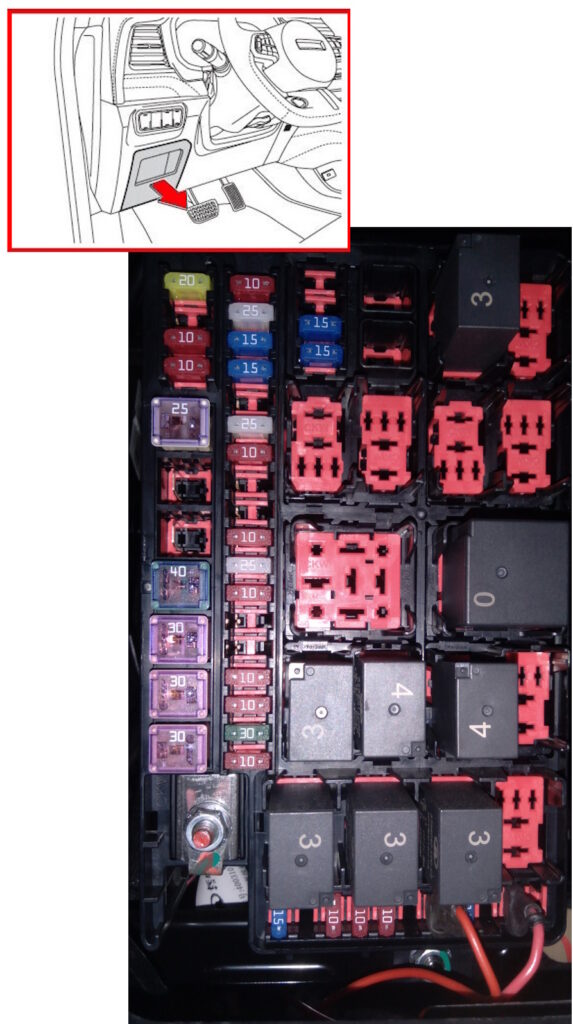
Check the assignment against your diagrams on the back of the protective cover.
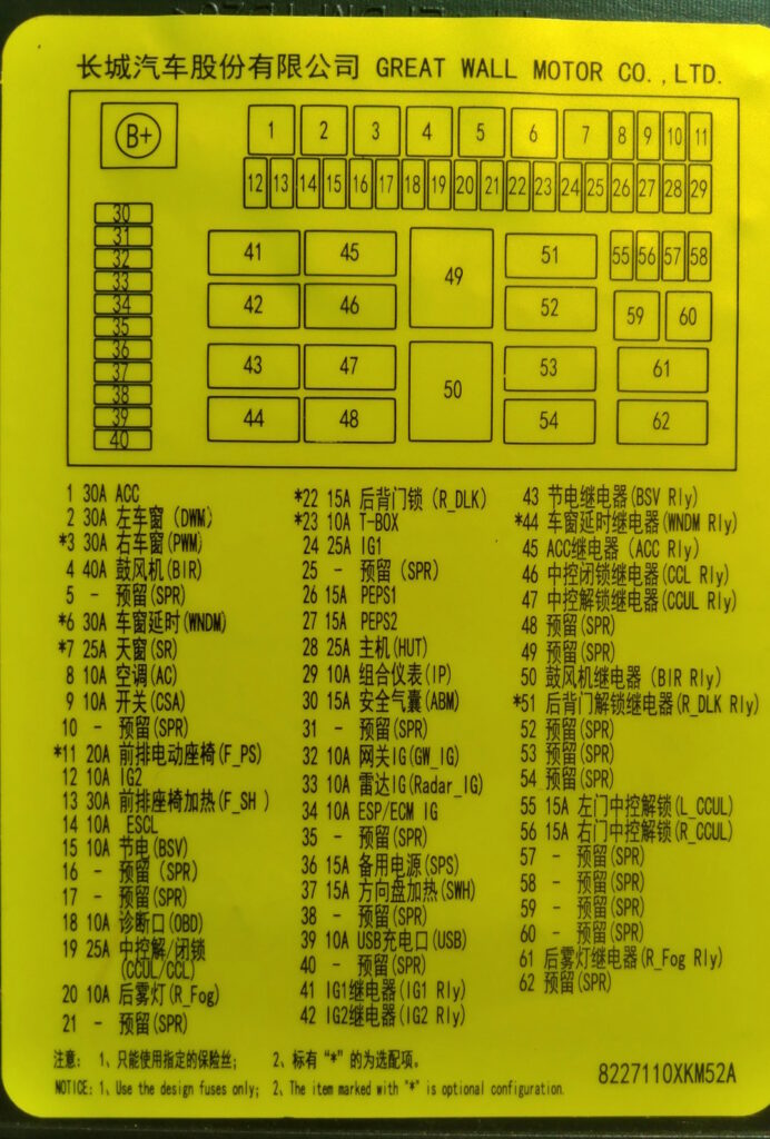
Diagram
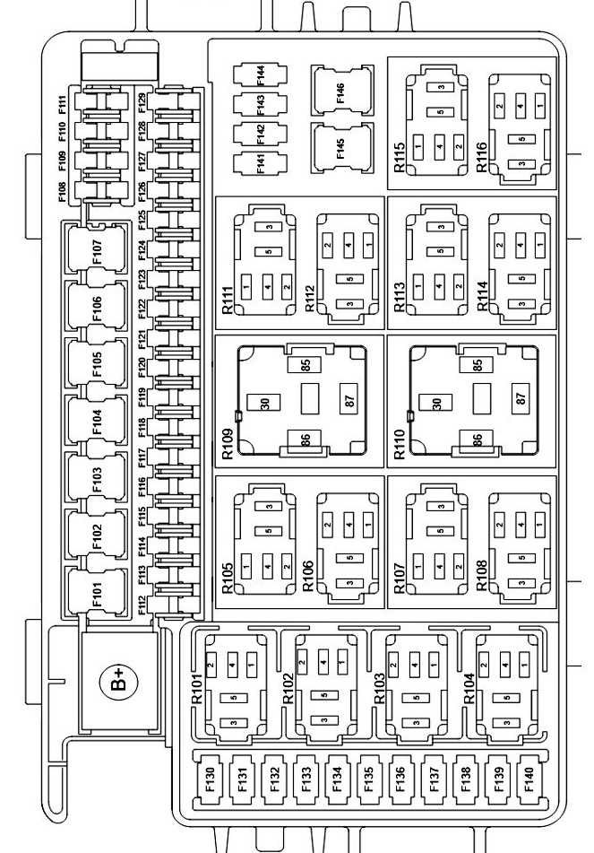
Designation
| F101 | ACC (accessory circuit: radio, USB, cigarette lighter) — 30A |
| F102 | Left door window switch — 30A |
| F103 | Right door window switch — 30A |
| F104 | Blower — 40A |
| F105 | Reserve |
| F106 | Power window delay relay — 30A |
| F107 | Sunroof — 25A |
| F108 | Climate control unit — 10A |
| F109 | Electronic transmission selector, central switch, front camera, RLS (rain and light sensor) — 10A |
| F110 | Reserve |
| F111 | Driver’s power seat — 20A |
| F112 | IG2 (second power circuit when ignition is on) — 10A |
| F113 | Heated front seats — 30A |
| F114 | Steering column lock — 10A |
| F115 | Power saver relay — 10A |
| F116 | Reserve |
| F117 | Reserve |
| F118 | OBD-II diagnostic connector — 10A |
| F119 | Central lock unlock — 25A |
| F120 | Rear Fog Light — 10A |
| F121 | Spare |
| F122 | Tailgate Lock — 15A |
| F123 | T-BOX (Telematics Module: GPS, GSM/LTE, Mobile App Communication) — 10A |
| F124 | IG1 (Main Power Circuit When Ignition is On) — 25A |
| F125 | Spare |
| F126 | PEPS1 (Keyless Entry and Start System) — 15A |
| F127 | PEPS2 (Keyless Entry and Start System) — 15A |
| F128 | HUT (Head Unit, Multimedia Display) — 25A |
| F129 | Instrument Cluster (Instrument Panel) — 10A |
| F130 | IG1-ABM (Ignition Circuit for ABS/ESP Module) — 15A |
| F131 | Spare |
| F132 | IG1-2 (IG1 Ignition Circuit, Line #2) — 10A |
| F133 | IG1-3 (IG1 Ignition Circuit, Line #3) — 10A |
| F134 | IG1-4 (IG1 ignition circuit, line #4) — 10A |
| F135 | Reserve |
| F136 | Auxiliary power socket — 15A |
| F137 | Heated steering wheel — 15A |
| F138 | Reserve |
| F139 | USB / ACC (USB port power and accessory circuit) — 10A |
| F140 | Reserve |
| F141 | Left door lock — 15A |
| F142 | Right door lock — 15A |
| F143 | Reserve |
| F144 | Reserve |
| F145 | Reserve |
| F146 | Reserve |
| R101 | IG1 relay — supplies power to the primary ignition circuits (IG1) after the ignition is turned on |
| R102 | IG2 relay — supplies power to the secondary ignition circuits (IG2) after the ignition is turned on |
| R103 | Power saving relay — disconnects some consumers when parked to prevent battery discharge |
| R104 | Power window delay relay — allows use of the power windows for a short time after the ignition is turned off |
| R105 | ACC (Accessories) relay — supplies power to accessory circuits: multimedia, USB, cigarette lighter, etc. |
| R106 | Lock relay Central Locking Relay – Controls door locking |
| R107 | Central Locking Unlock Relay – Controls door unlocking |
| R108 | Reserve |
| R109 | Reserve |
| R110 | Fan Relay – Turns on the engine cooling fan |
| R111 | Tailgate Lock Relay – Controls the electric tailgate lock |
| R112 | Reserve |
| R113 | Reserve |
| R114 | Reserve |
| R115 | Rear Fog Light Relay – Turns on the rear fog light |
| R116 | Reserve |
Engine compartment
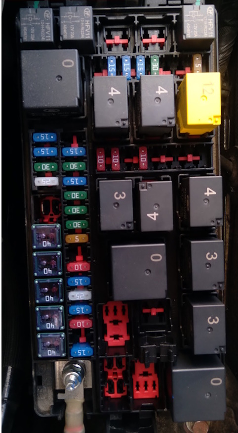
In the engine compartment, under the bonnet on the left side near the battery, there is the main fuse and relay box.
Photo example
Example of a diagram from the block cover
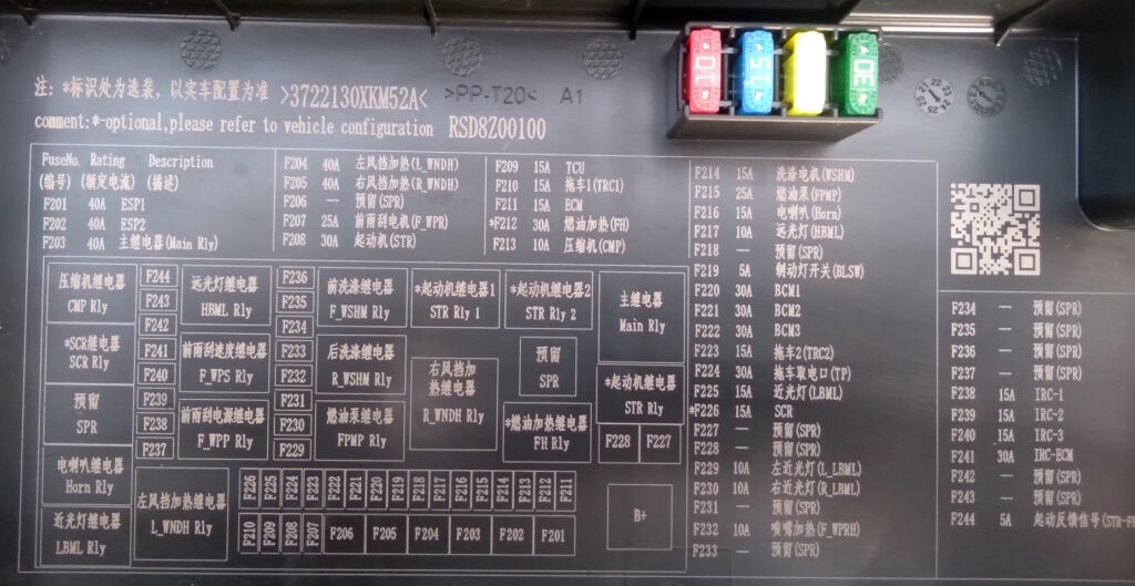
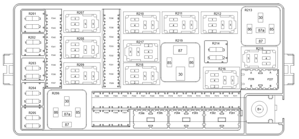
Diagram
Assignment
| F201 | ESP1 (Stability Control) — 40A |
| F202 | ESP2 (Stability Control) — 40A |
| F203 | Main Relay — 40A |
| F204 | Heated Left Windshield — 40A |
| F205 | Heated Right Windshield — 40A |
| F206 | Spare |
| F207 | Wiper Motor — 25A |
| F208 | Starter — 30A |
| F209 | TCU (Transmission Control Unit) — 15A |
| F210 | Trailer 1 — 15A |
| F211 | ECM (Engine Control Unit) — 15A |
| F212 | Fuel Preheater — 30A |
| F213 | A/C Compressor — 10A |
| F214 | Washer Pump — 15A |
| F215 | Fuel Pump — 25A |
| F216 | Horn — 15A |
| F217 | High Beam Headlights — 10A |
| F218 | Spare |
| F219 | Brake Light Switch — 5A |
| F220 | BCM-1 (Body Control Module) — 30A |
| F221 | BCM-2 (Body Control Module) — 30A |
| F222 | BCM-3 (Body Control Module) — 30A |
| F223 | Trailer 2 — 15A |
| F224 | Trailer Power Socket — 30A |
| F225 | Right Low Beam Headlight — 15A |
| F226 | SCR (Supplemental Control System) — 15A |
| F227 | Spare |
| F228 | Spare |
| F229 | Left Low Beam Headlight — 10A |
| F230 | Right Low Beam Headlight — 10A |
| F231 | Spare |
| F232 | Windshield Washer Nozzle Heater — 10A |
| F233 | Spare |
| F234 | Spare |
| F235 | Spare |
| F236 | Spare |
| F237 | Spare |
| F238 | IRC-1 — 15A |
| F239 | IRC-2 — 15A |
| F240 | IRC-3 — 15A |
| F241 | ECM (Engine Control Module) — 30A |
| F242 | Spare |
| F243 | Spare |
| F244 | Engine Start Feedback Signal — 5A |
| R201 | A/C Compressor Relay |
| R202 | SCR Relay (Supplemental Control System) Diesel) |
| R203 | Reserve |
| R204 | Horn relay |
| R205 | Low beam headlight relay |
| R206 | Left windshield defroster relay |
| R207 | Wiper power relay |
| R208 | Wiper speed relay |
| R209 | High beam headlight relay |
| R210 | Windshield washer pump relay |
| R211 | Gasoline engine starter relay #1 |
| R212 | Gasoline engine starter relay #2 |
| R213 | Main engine management system relay |
| R214 | Reserve |
| R215 | Starter relay |
| R216 | Fuel heater relay |
| R217 | Rear window washer relay |
| R218 | Fuel pump relay |
| R219 | Right windshield defroster relay |
A high-power fuse block in the form of fusible links can be mounted on the positive terminal of the battery.
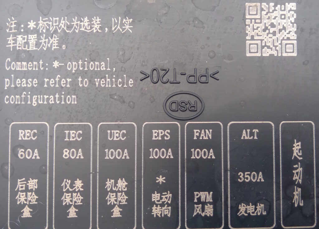
Diagram
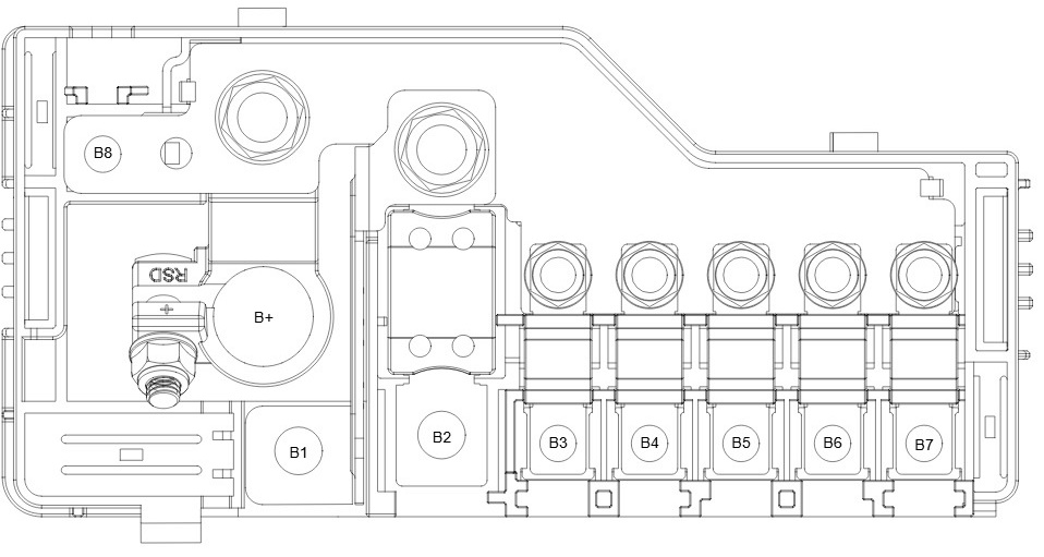
Allocation
- B1 – Starter
- B2 – Alternator 350A
- B3 – Fan 100A
- B4 – Electric Power Steering* 100A
- B5 – Engine Compartment Fuse Box 100A
- B6 – Instrument Panel Fuse/Relay Box 80A
- B7 – Luggage Compartment Fuse Box 60A
- B8 – Pre-Glow* 80A
Luggage compartment
Another fuse box can be installed in the luggage compartment on the left side.
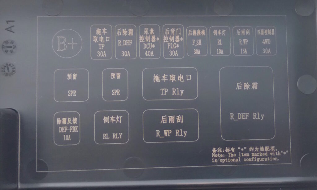
Diagram
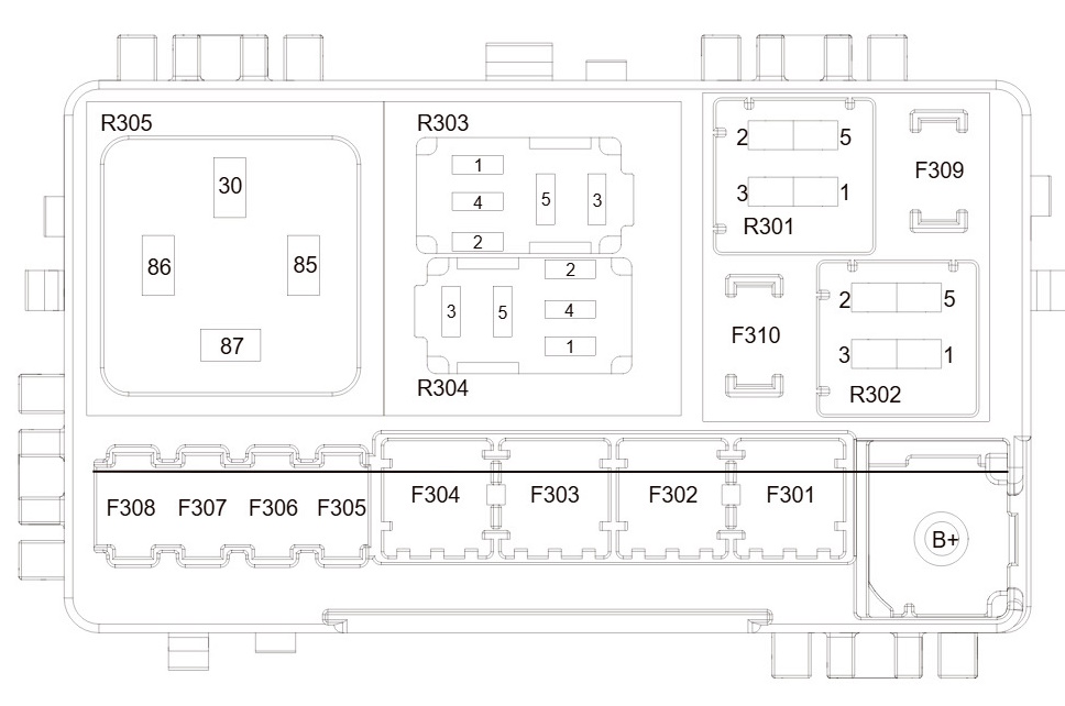
Description
| F301 | Trailer Power Socket – 30A |
| F302 | Rear Window Defogger – 30A |
| F303 | Urea Injection Controller* – 40A |
| F304 | Tailgate Controller* – 30A |
| F305 | Rear Seats – 30A |
| F306 | Reversing Light – 10A |
| F307 | Rear Window Wiper – 15A |
| F308 | All-Wheel Drive Control Module – 30A |
| F309 | Windshield Defogger Feedback – 10A |
| F310 | Spare |
| R101 | Reversing Light Relay |
| R102 | Spare |
| R103 | Rear Window Wiper Relay |
| R104 | Trailer Power Socket Relay |
| R105 | Rear Window Defogger Relay |
If you spot a mistake or have something to add, please leave a comment. We also have a video on this topic on our channel.