The 1st generation Mercedes-Benz Sprinter was produced in 1995, 1996, 1997, 1998, 1999, 2000, 2001, 2002, 2003, 2004, 2005 with various body styles designated W901 / W902 / W903 / W904 / W905. During this time, the model was updated 2 times. In this post you will find a description of the fuses and relays Mercedes Sprinter 1 with box diagrams, their photo examples and locations. Select the fuses for the cigarette lighter and fuel pump.

The design of the boxes and the purpose of the elements in them may differ from those presented and depend on the year of manufacture and the level of equipment of your car.
Not suitable generation or diagram?
[Description of Sprinter 2G]
[Description of Sprinter 3G]
Fuse box under the panel
The first fuse and relay box is installed under the panel. To access, remove the protective cover.

Type 1
Diagram

Assignment
| 1 | Right rear position lamp and right parking light – 15 A. |
| 2 | High beam right headlight – 15 A. |
| 3 | High beam left headlight, signal light – 15 A. |
| 4 | Reversing lights – 15 A. |
| 5 | Stop lights – 15 A. |
| 6 | Wiper motor – 20 A. |
| 7 | Heated rear window, signal – 15 A. |
| 8 | Interior lamp, cigarette lighter, radio tape recorder – 20 A. |
| 9 | Clock, emergency light signaling, parking lights – 20 A. |
| 10 | Illumination of the instrument panel, license plate lights, daytime running lights – 15 A. |
| 11 | Left rear position lamp and left parking light – 15 A. |
| 12 | Dipped beam of the right headlight – 15 A. |
| 13 | Dipped beam left – 15 A. |
| 14 | Fog lamp, rear fog lamp – 15 A. |
| 15 | Radio tape recorder – 15 A, |
| 16 | Reserve |
| 17 | Reserve |
| 18 | Reserve |
For the cigarette lighter, fuse number 8 is responsible for 20A.
Separate relays can be located under this fuse box (window wiper and turn signal relays.).

Type 2
Diagram

Designation
| 1 | 10A Right parking light, right tail light |
| 2 | 10A High beam right headlight |
| 3 | 10A High beam left headlight, high beam indicator light |
| 4 | 10A Reversing lamp |
| 5 | 10A Stop lights |
| 6 | 20A Wiper motor |
| 7 | 15A Horn, heated rear window, accessories relay (circuit 15) |
| 8 | 20A Interior lamp, cigarette lighter; radio (chain 30) |
| 9 | 15A Clock, hazard warning lights, parking light |
| 10 | 10A Instrument panel illumination, license plate light, daytime driving light |
| 11 | 10A Left parking light, left rear position light |
| 12 | 10A Dipped beam right headlight |
| 13 | 10A Low beam left headlight |
| 14 | 15A Fog lamps, rear fog lamp |
| 15 | 10A Radio receiver (circuit 15) |
| 16 | 25A Diesel engine control unit (circuit 30) |
| 17 | 15A Engine control unit (circuit 30) |
| 18 | 15A Ignition (circuit 15) |
| 19 | 15A Gasoline pump (circuit 30) |
| 20 | 15A Heating control panel (circuit 30) |
| 21 | 30A Heating fan, front (circuit 30) |
For the cigarette lighter, fuse number 8 is responsible for 20A.
Relays are attached at the bottom:
- Windscreen wipers
- Engine control
- Direction indicators, hazard
Box under the seat
Type 1
The additional relay and fuse box is located under the driver’s seat behind a protective cover.
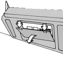
Photo example

Diagram

Decoding
| R1 | Horn relay |
| R2 | Special equipment |
| R3 | Coolant pump relay |
| 1 | 7.5A Combined meter |
| 2 | 25A Additional heater |
| 3 | 7.5A Buzzer |
| 4 | 7.5A Buzzer |
| 5 | 10A Additional heater |
Type 2
Diagram

Appointment
| 9.1 | |
| F7 | ESP, terminal 30 |
| F11 | instrument cluster |
| F900 | Terminal 30 |
| F85 | Daytime running lights, terminal 30 |
| F43 | Remote radio control |
| F112 | Central locking system, terminal 30 |
| F100 | Central locking system, terminal 30 |
| F44 | Central locking systems |
| F101 | Additional liquid heater |
| 9.2 | |
| F115 | Terminal D+ |
| F158 | Fuel pump |
| F300 | Interior lighting |
| F70 | Relay el. circuit terminal D+ |
| F114 | Additional heat exchanger |
| F110 | trailer socket |
| F155 | Additional heater |
| F143 | Additional liquid heater |
| F19 | Additional turn signal module II |
| 9.3 | |
| F116 | Terminal 30 |
| F117 | Terminal 15 |
| F180 | Terminal 30 |
| F52 | Front passenger door window regulator |
| F53 | Driver’s door power window |
| F54 | Heated and adjustable exterior mirrors |
| F86 | Daytime running lights, terminal 15 |
| F87 | Left headlight |
| 9.4 | |
| F88 | Right headlight |
| F89 | Relay terminal 87 (1) |
| F90 | Relay terminal 87 (2) |
| F91 | Relay terminal 87 (3) |
| F128 | Heated driver’s seat |
| F139 | Additional liquid heater |
| F150 | Roof fan |
| F163 | Tachograph, terminal 30 |
| F164 | Tachograph, terminal 15 |
| 9.5 | |
| F5 | ESP |
| F119 | Additional air conditioning fan |
| F6 | ESP, terminal 30 |
| Relay | |
| K26 | Relay terminal D+ |
| K61 | Starter relay |
| K87 | Relay terminal 87 |
Under the driver’s seat, some additional relays can be installed.
We also posted a video on our YouTube channel. Look and subscribe.
That’s all. And if you have something to add – write in the comments.
Hello
I am wanting to know if my Sprinter 2005 has a relay fuse for the heater blower fan other than the the fuse numbered 21?
Are the fuses located under the driver side seat relay fuses and would one be for the heater blower fan? There are 3 in your diagram K26, K61, K87.
I have replaced the variable resistor and the blower fan is working.
Thanks
Ken
Where is the inhibitor relay located on a Mercedes sprinter 2002?
Sprinter 2003 2.7 Cdi 216, I’m looking for relay of horn, the fuse is number 7 and is ok, and relay I suppose is K14 but i don’t know where is it:
Thanks and regards
Check under the steering wheel . Behind the light and steering wheel there is a small needle-like iron who touch the steering wheel