The 3rd generation Kia Optima was introduced in 2010. Produced in 2011, 2012, 2013, 2014 and 2015. Also known as Kia Magentis. During this time, the model has been restyled. In this article, we will present for review a designation of the 3rd generation Kio Optima fuses and relays with boxes diagrams and their locations. Let’s highlight the fuse responsible for the cigarette lighter.

The current box diagrams and the purpose of their elements will be presented on the reverse side of the protective cover, check the designation.
Contents
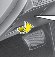
Passenger compartment
It is located in the passenger compartment, under the dashboard, on the driver’s side, behind the protective cover.

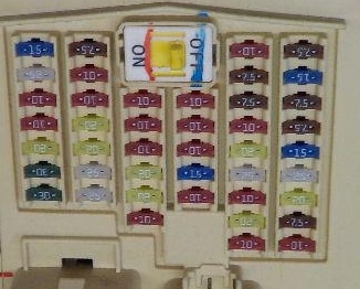
Type 1

Check the assignment against your diagrams on the back of the protective cover.

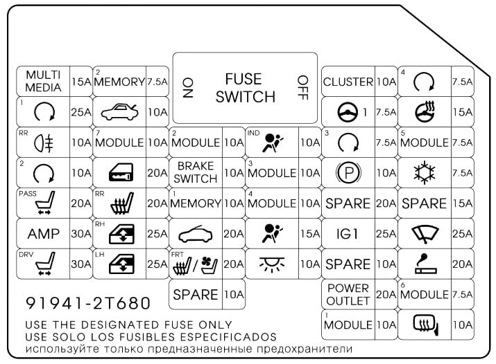
Type 2
Diagram
Protected components
| F1 MODULE 3 | Sport Mode Switch, Key Lock Solenoid (w / o e-key) |
| F2 Start | Control unit el. key (with e-key) |
| F3 Power socket | Front power outlet |
| F4 MODULE 5 | Control unit el. key (with smart key), rear seat heater relay left / right, engine compartment fuse and relay box (relay 2) |
| F5 MODULE 2 | ВСМ (body electrical equipment control unit), panoramic sunroof, rain sensor |
| F6 SPARE | Spare |
| F7 Trunk | Trunk lid relay, fuel filler flap and trunk opener switch, trunk lid opener motor, ICM relay box (fuel filler flap open relay) |
| F8 Clock | Decorative lamp for driver / passenger door, electric outside mirror switch, air conditioning control unit, decorative lamp for instrument panel extension, ceiling console lamp, amplifier, BCM (control unit for body electrical equipment), electronic control unit. key (with electronic key), audio system, audio-visual head unit with navigation |
| F9 Cigar | Cigarette lighter |
| F10 Heating steering wheel an arm. | Steering wheel heater |
| F11 Snowflake | Air conditioning control module, relay and fuse box M / O (RELAY 14) |
| F12 Brush | Relay and fuse box M / O (RELAY 11/12), multi-function switch, front wiper motor |
| F13 Obr. seating | Heated driver / passenger seat cushion with climate control (with climate control seats), driver / passenger seat heater module (without climate control seats) |
| F14 Spare | Spare |
| F15 Mirror | Power outside mirror, driver / passenger side |
| F16 MODULE 4 | Driver / passenger seat cushion heater with climate control (with seat climate control), driver / passenger seat heater module (without seat climate control), front seat heater and seat climate control switch |
| F17 Indicator | Instrument cluster |
| F18 Start | Control unit el. key (with electric key), alarm relay (without electric key) |
| F19 Gr. seating | Rear seat heater relay LEFT / RIGHT |
| F20 Seat | Passenger seat manual switch |
| F21 Against headlights | Rear fog lamp relay |
| F22 MODULE 1 | Drive of the left / right headlight tilt angle corrector, BCM unit, automatic headlight range control unit (HLLD auto), manual headlight range control unit (HLLD), automatic transmission lever position indicator, instrument cluster, electrochromic mirror, integrated module driver seat memory systems, rear parking aid buzzer, air conditioning control unit, lane keeping system module, parking aid module |
| F23 Empty | Reserve |
| F24 Indicator | PSB control module, seat belt reminder indicator (right-hand drive), warning light (Europe) |
| F25 Door glass | Driver window module with power anti-pinch glass (left hand drive), passenger window module with power glass with anti-pinch protection (right hand drive), left rear door window module with power anti-pinch glass, relay left electric glass lifter |
| F26 Forced. | Amplifier |
| F27 Start | Control unit el. key, key fob holder, start and stop button |
| F28 Spare | Spare |
| F29 MDPS | Instrument Panel Extension Switch, EPS Control Module (with MDPS), Steering Angle Sensor (without MDPS) |
| F30 Start | Control unit el. key (with e-key) |
| F31 Glass door | Driver window module with power anti-pinch glass (right hand drive), passenger window module with power glass with anti-pinch protection (left hand drive), right rear door window module with power anti-pinch glass, relay for right electric glass lifter |
| F32 Seat | Driver’s seat IMS module, driver’s seat manual mode switch, driver’s seat lumbar support switch (2-way) |
| F33 Door lock | Door lock relay, door unlock relay, turn signal horn relay, double lock relay (right side control) |
| F34 Luke | Panoramic sunroof |
| F35 ING 1 | Engine compartment relay and fuse box (F11-10A, F12-15A, F13-10A) |
| F36 Audio system | Audiovisual head unit with navigation |
| F37 Interior lamp | External handle el. driver / passenger door key (with electric key), driver / passenger door lamp, air conditioning control unit, ignition key illumination and door opener switch (without electric key), radio frequency receiver (with electric key), driver IMS unit, VSM , Power Mirror Switch, Auto Lamp Off Relay, Data Link Connector, Driver / Passenger Threshold Lamp, Instrument Cluster, Auto Lights On and Photocell (Alarm Arm) |
Relay
On the back of the unit, there can be separate relays: the relay for the left and right windows with a glass servo, the relay for the trunk lid and the door lock relay.
Engine compartment
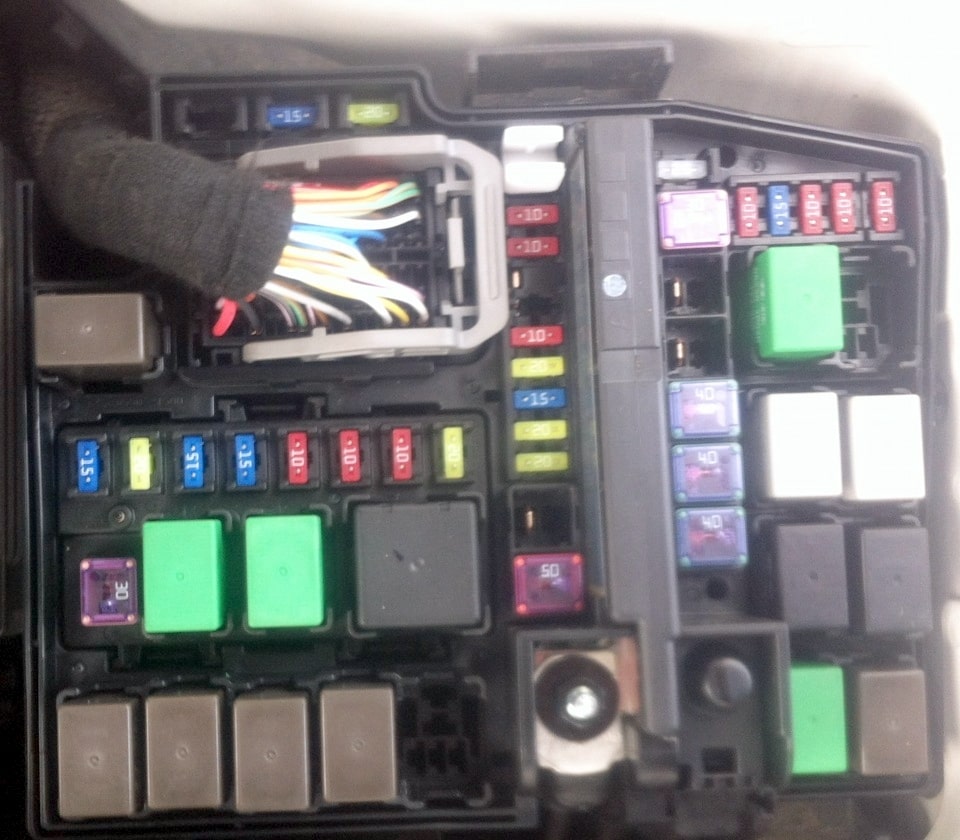
Main fuse box
Located on the left side of the engine compartment.
 Photo for example
Diagram
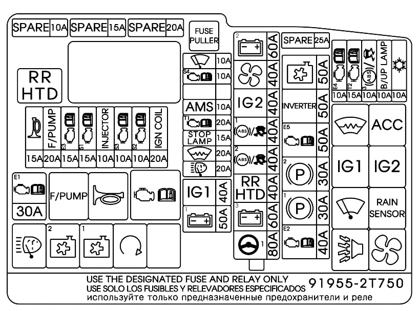
Assignment
| IP B+ 2 | 60A I/P Junction Box (P/SEAT DRV 30A, P/SEAT PASS 20A, AMP 30A, PDM 2 7.5A, IPS 5, IPS 6, ARISU 2) |
| B+ 4 (Not Used) | 60A |
| IGN 2 | 40A E/R Fuse & Relay Box (Start Relay), Fuse & Relay Box (PDM 3(IG 2) Relay), Ignition Switch |
| ABS 1 | 40A ESC Module |
| RR HTD (G4KJ)/ C/FAN HI (G4KH) | 40/60A E/R Fuse & Relay Box (RR HTD Relay) (G4KJ) C/FAN (HI) Relay (G4KH) |
| BLOWER | 40A E/R Fuse & Relay Box (Blower Relay) |
| IP B+ 1 | 60A I/P Junction Box (PDM 1 25A, MODULE 3 7.5A, S/HEATER FRT 20A, S/HEATER RR 15A TRUNK 10A, P/WDW LH 25A, P/WDW RH 25A), Power Connector (AUDIO 15A)) |
| MDPS | 80A EPS Control Module |
| FUSES: | |
| WIPER | 10A PCM |
| RR HTD IND | 10A A/C Control Module |
| AMS | 10A Battery Sensor |
| TCU 1 | 10A PCM |
| STOP LP | 10A E/R Fuse & Relay Box (HAC Relay), Smart Key Control Module, Stop Lamp Switch |
| DEICER | 10A E/R Fuse & Relay Box (Deicer Relay) |
| H/LP WASHER | 10A |
| LDC 1 | 30A |
| C/FAN | 40A E/R Fuse & Relay Box (C/Fan(HI) Relay, C/Fan(LO) Relay) |
| ABS 2 | 30A Multipurpose Check Connector, ESC Module |
| LDC 2 | 30A |
| CVVL(Not Used)/ RR THD (G4KH) | 40A RR HTD Relay (G4KH) |
| IPB+3 | 50A I/P Junction Box (Power Connector (ROOM LP 10A), SUNROOF 20A, DR LOCK 20A IPS 1, IPS 3, ARISU 1) |
| IGN 1 | 40A Fuse & Relay Box (PDM 1(ACC) Relay, PDM 2(IG 1) Relay), Ignition Switch |
| EMS | 40A EMS Box (HORN 15A, ECU 3 10A, ECU 1 30A, F/PUMP 20A) |
| ECU 4 | 10A PCM |
| TCU 2 | 15A Back-Up Lamp Switch, Vehicle Speed Sensor, Transaxle Range Switch |
| ABS 3 | 10A E/R Fuse & Relay Box (HAC Relay), Stop Lamp Switch, ESC Module, Multipurpose Check Connector |
| B/UP LP | 10A A/V & Navigation Head Unit, Audio, Electro Chromic Mirror, BCM, Rear Combination Lamp(ln) LH/RH |
| A/CON | 10A A/C Control Module |
Relay layout

Relay designation
- Front window defogger relay
- Relay block SMK
- HAC relay
- Rain sensor relay
- Fan relay
- Horn relay
- Wiper relay
- Reserve
- Reserve
- Start relay
- Air conditioner fan relay (low speed)
- A / C Fan Relay (High Speed)
- Fuel pump relay
- Signal relay
- Heated rear window relay
- Engine control relay
- Start Button Relay 1 (ACC)
- Start Button Relay 2 (IG1)
- Start Button Relay 3 (IG2)
- Reserve
Additional box
Installed at the front of the engine compartment on diesel models.

Diagram

Decoding
- 80A – glow plugs
- PTC HEATER – heater (additional heater)
- 30A – fuel filter
Main fuse
The main power fuse is located on the positive terminal of the battery and is designed as a fusible link.

If the diagrams have othe style study the description for the 4th generation Kia Optima .
Still have questions? Ask them in the comments.
What fuse controls the headlamps/ head lights. Nothing clearly states this. My low beams went out at the same time, but my high beams do not work. I have a 2015 Kia optima.