The 10G F-Series was introduced in January 1996 as a 1997 model. Years of production: 1998, 1999, 2000, 2001, 2002 and 2003. During this time the model was redesigned. In this article you will find an assignment of the Ford F150 fuses and relays with box diagrams and element designation. Note the cigarette lighter fuse.

The purpose of the elements in the boxess may differ from the one shown. Compare with your diagrams on the back of the protective cover or other technical documentation.
Is it the wrong generation or the diagrams are not suitable? See other Ford F-150:
[ Ford F-150 14G (2021-2026) ]
[ Ford F-150 13G (2015-2020) ]
[ Ford F-150 12G (2009-2014) ]
[ Ford F-150 11G (2004-2008) ]
Contents
Passenger compartment
Fuse box
The fuse panel is located below and to the left of the steering wheel by the brake pedal. Remove the panel cover to access the fuses. To remove a fuse use the fuse puller tool provided on the fuse panel cover.

Type 1
1997, 1998
Diagram

Designation
| 1 | 15A Flasher Relay(Stop/ turn lamps and turn indicators) |
| 2 | 5A Instrument Cluster |
| 3 | 25A Cigar Lighter |
| 4 | 5A Park Lamp Relay, Headlamp Relay, Autolamp Module Remote Anti-Theft Personality (RAP) Module, Power Mirror Switch |
| 5 | 15A Digital Transmission Range (DTR) Sensor (A/T), Backup Lamp Switch (M/T), Daytime Running Lights (DRL) Module, Speed Control Servo/Amplifier Assembly, Heater-A/C Control Assembly, Blend Door Actuator |
| 6 | 5A Shift Lock Actuator, Generic Electronic Module (GEM), Rear Air Suspension (RAS) Module |
| 7 | Not Used |
| 8 | 5A Radio, Main Light Switch, Remote Anti-Theft Personality (RAP) Module |
| 9 | Not Used |
| 10 | Not Used |
| 11 | 30A Washer Pump Relay, Wiper Run/Park Relay, Wiper Hi/LO Relay, Windshield Wiper Motor |
| 12 | 5A Data Link Connector (DLC) |
| 13 | 15A Rear Anti-Lock Brake System (RABS) Module, Brake On/Off (BOO) Switch, Brake Pressure Switch |
| 14 | 15A Batteiy Saver Relay, Interior Lamp Relay |
| 15 | 5A Generic Electronic Module (GEM) |
| 16 | 20A Instrument Cluster (W/O DRL), Daytime Running Lamps (DRL) Module, Hi-Beam Headlamps (Power supplied through Multi-Function Switch) |
| 17 | Not Used |
| 18 | 5A Park Lamp Relay, Trailer Electronic Brake Controller, Main Light Switch, Trailer Tow Run Relay, Front Park/Turn Lamps, License Lamps, Stop/Park/Turn Lamps, Tail/Side Marker Lamps (Power supplied through Main Light Switch) |
| 19 | 10A Instrument Cluster, Air Bag Diagnostic Monitor |
| 20 | 5A Powertrain Control Module (PCM), Generic Electronic Module (GEM)/Central Timer Module (CTM) |
| 21 | 15A Clutch Pedal Position (CPP) Switch (W/O RAP), Starter Interrupt Relay (W/RAP) |
| 22 | 10A Air Bag Diagnostic Monitor, Passive De-Activation (PAD) Module |
| 23 | 10A Trailer tow Batteiy Charge Relay, 4X4 Hub Solenoid, 4X2 Hub Solenoid, Flasher Relay, Shift on the Fly Relay |
| 24 | 10A Blower Relay |
| 25 | 5A 4 Wheel Anti-Lock Brake System (4WABS) Module, 4WABS Relay |
| 26 | 10A Daytime Running Lamps (DRL) Module, Right Headlamp |
| 27 | 5A Main Light Switch, Fog Lamp Relay |
| 28 | 10A Left Headlamp |
| 29 | 5A Autolamp Module, Instrument Cluster, Transmission Control Switch (TCS), Brake Warning Resistor/Diode Assembly (W/RABS) |
| 30 | 30A Radio Noise Capacitor, Ignition Coil, PCM Power Diode |
| 31 | Not Used |
| Relay 1 | Interior Lamp Relay |
| Relay 2 | Batteiy Saver Relay |
| Not Used | |
| Relay 4 | One Touch Down Relay |
| Relay 5 | ACC Delay Relay |
Fuse №3 (Cigarette lighter) in the Instrument panel fuse box, and fuse №10 (Auxiliary power point) in the Engine compartment fuse box.
Type 2
Diagram

Assignment
| 1 | 15A Audio |
| 2 | 5A Powertrain Control Module (PCM), Cluster |
| 3 | 20A Cigar lighter, Data link connector |
| 4 | 5A Power mirror switch, Mirror turn signal relays |
| 5 | 15A Speed control module, Reverse lamp, Climate mode switch, Daytime Running Lamps (DRL) relay, Digital Transmission Range (DTR) sensor |
| 6 | 5A Cluster, Brake shift interlock solenoid, GEM |
| 7 | Not used |
| 8 | 5A Radio, Remote entry module, GEM, In-vehicle entertainment system (SuperCrew only) |
| 9 | Not used |
| 10 | Not used |
| 11 | 30A Front washer pump relay, Wiper run/park relay, Wiper HI/LO relay, Windshield wiper motor |
| 12 | Not used |
| 13 | 20A Stop lamp switch (Lamps), Turn/Hazard flasher |
| 14 | 15A Battery saver relay, Interior lamp relay |
| 15 | 5A Stop lamp switch (speed control, brake shift interlock), GEM, Rear Anti-lock Brake System (RABS) module |
| 16 | 20A Headlamps (hi beams), Cluster (hi beam indicator) |
| 17 | Not used |
| 18 | 5A Instrument illumination (dimmer switch power) |
| 19 | Not used |
| 20 | 5A Audio, GEM, PCM, Transmission range sensor |
| 21 | 15A DTR sensor, Clutch switch, Starter relay, I/P fuse 20 |
| 22 | 10A Air bag module, Passenger air bag deactivation module |
| 23 | 10A Trailer tow battery Charge relay, Turn/Hazard flasher, 4×4 solenoids, 4×4 relays, Overhead console, 4-Wheel Anti-lock Brake System (4WABS) module, EC mirror, Heated seats |
| 24 | 10A Function selector switch assembly |
| 25 | 10A Heated mirrors |
| 26 | 10A Right-hand low beam headlamp |
| 27 | 5A Foglamp relay and foglamp indicator, Main light switch (upstream) |
| 28 | 10A Left-hand low beam headlamp |
| 29 | 5A Autolamp module, Transmission overdrive control switch, Central security module, Beltminder |
| 30 | 30A Passive Anti-theft transceiver, Cluster, Ignition coils, PCM relay, Coil on plugs, Radio noise capacitor, ECC diode |
| 31 | Not used |
| Relay 1 | Interior lamp relay |
| Relay 2 | Battery saver relay |
| Relay 3 | Not used |
| Relay 4 | One-touch down window relay |
| Relay 5 | Accessoiy delay relay |
Fuse №3 (Cigarette lighter) in the Instrument panel fuse box, and fuses №1 (Power Point), №12 (Rear Auxiliary Power Point) in the Engine compartment fuse box.
Relay box
Individual fuses and relays can be located outside the main fuse box. For example, some boxes can be attached behind the left side of an instrument panel.

or

Relay box 4: indicator flasher relay (c2047) and blower motor relay (c2017)
Engine compartment
Type 1
Engine minifuse panel
It is located behind the power distribution box.
Diagram

Protected components
- 5A Powertrain control module (PCM)
- 20A Trailer tow stop/turn lamps
Primary battery fuses
They are located under the PRIMARY BATTERY FUSE cover next to starter relay.
Diagram

Functions
- 175A Power network box megafuse
- 175A Alternator megafuse
- 20A Alternator field minifuse
Power distribution box
The power distribution box is located in the engine compartment. The power distribution box contains high-current fuses that protect your vehicle’s main electrical systems from overloads.

Diagram

Assignment
| 4 | 15A Rear Air Suspension (RAS) |
| 5 | 20A Horn Relay |
| 6 | 15A Radio, Premium Sound Amplifier, CD Changer |
| 7 | 15A Main Light Switch, Park Lamp Relay |
| 8 | 30A Main Light Switch, Headlamp Relay, Multi-Function Switch |
| 9 | 15A Daytime Running Lamps (DRL) Module, Fog Lamp Relay |
| 10 | 25A Auxiliary Power Socket |
| 11 | Not Used |
| 12 | Not Used |
| 13 | Not Used |
| 14 | 20/60A 4 Wheel Anti-Lock Brake System (4WABS) Module/Ignition Switch (W/RABS Only) |
| 15 | 50A Rear Air Suspension Compressor |
| 16 | 40A Trailer Tow Batteiy Charge Relay, Engine Fuse Module (Fuse 2) |
| 17 | 30A Shift on the Fly Relay, Transfer Case Shift Relay |
| 18 | 30A Power Seat Control Switch |
| 19 | 20A Fuel Pump Relay |
| 1 | 20A Trailer Tow Running Lamp Relay, Trailer Tow Backup Lamp Relay |
| 2 | 10A Air Bag Diagnostic Monitor |
| 3 | 15A All Unlock Relay, All Lock Relay, Driver Unlock Relay, LH Power Door Lock Switch, RH Power Door Lock Switch |
| 20 | 50A Ignition Switch |
| 21 | 50A Ignition Switch |
| 22 | 50A Junction Box Fuse/Relay Panel Batteiy Feed |
| 23 | 40A Blower Relay |
| 24 | 30A PCM Power Relay, Engine Fuse Module (Fuse 1) |
| 25 | 30A Junction Box Fuse/Relay Panel, ACC Delay Relay |
| 26 | Not Used |
| 27 | Not Used |
| 28 | 30A Trailer Electronic Brake Controller |
| 29 | Not Used |
Type 2
Photo

Diagram
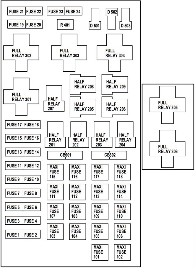
Designation
| 1 | 20A Power point |
| 2 | 30A Powertrain Control Module (PCM) |
| 3 | 30A Main light switch, Headlamp relay, Multifunction switch |
| 4 | 20A Console power point (Harley Davidson only) |
| 5 | 20A Trailer tow back-up/park lamps |
| 6 | 15A Main light switch, Park lamp relay |
| 7 | 20A Horn |
| 8 | 15A Power door locks, Central Security Module (CSM), Lock relays (not used on SuperCrew) |
| 9 | 15A Daytime Running Lamps (DRL), Fog lamps |
| 10 | 20A Fuel pump |
| 11 | 20A Alternator field |
| 12 | 20A Rear auxiliary power point (SuperCrew only) |
| 13 | 15A A/C clutch |
| 14 | Not used |
| 15 | 10A Running board lamps |
| 16 | 15A Bi-fuel injector module, fuel selector switch and alternative fuel injectors (Bi-fuel vehicles only) |
| 17 | Not used |
| 18 | 15A PCM, Fuel injectors, Fuel pump relay, Mass air flow sensor |
| 19 | 10A Trailer/Camper adapter (right stop/turn lamp) |
| 20 | 10A Trailer/Camper adapter (left stop/turn lamp) |
| 21 | Not used |
| 22 | Not used |
| 23 | 15A HEGO sensor, Automatic transmission |
| 24 | Not used |
| 101 | 30A Trailer tow battery charge |
| 102 | 20/50A Four-wheel Anti-lock Brake System (4WABS) module/ Rear-wheel Anti-lock Brake System (RABS) module, Ignition switch |
| 103 | 50A Central junction box |
| 104 | 30A 4×4 shift motor & clutch |
| 105 | 40A Climate control front blower |
| 106 | 20A Intercooler pump (supercharged engine only) |
| 107 | Not used |
| 108 | 30A Trailer tow electric brake |
| 109 | Not used |
| 110 | 30A Accessoiy delay relay (Not used on SuperCrew) |
| 111 | 40A Ignition switch battery feed (start and run circuits) |
| 112 | 30A Drivers power seat, Adjustable pedal switch |
| 113 | 40A Ignition switch battery feed (run and accessory circuits) |
| 114 | Not used |
| 115 | 20A Power door locks (SuperCrew only) |
| 116 | 40A Heated backlight |
| 117 | 40A Audiophile radio (SuperCrew only) |
| 118 | 30A Heated seats |
| 201 | Trailer tow park lamp relay |
| 202 | Front wiper run/park relay |
| 203 | Trailer tow backup lamp relay |
| 204 | A/C clutch relay |
| 205 | Horn relay |
| 206 | Fog lamp relay |
| 207 | Front washer pump relay |
| 208 | Intercooler pump relay (supercharged engine only) |
| 209 | Front wiper HI/LO relay |
| 301 | Fuel pump relay |
| 302 | Trailer tow battery charge relay |
| 303 | Heated backlight relay (SuperCrew only) |
| 304 | PCM relay |
| 305 | Fuel pump HI/LO relay (supercharged engine only) |
| 306 | Inertia switch relay (supercharged engine only) |
| 401 | Not used |
| 501 | PCM diode |
| 502 | A/C compressor diode |
| 503 | Not used |
| 601 | Power windows, Moonroof (SuperCrew only) |
| 602 | Not used |
We also prepared a video on our channel. Watch and subscribe!
Users Manual
Still have questions?
You can find more information in Users Manual or ask questions in the comments.