Production of the third generation Audi A8 was launched in 2010. This series was designated as D4 / 4H. Compared to the previous series, the design of the A8 has remained practically unchanged. Released in 2011, 2013, 2014, 2015, 2016, 2017, 2018, 2019. Description of fuses Audi A8 D4 will be presented in our material in the form of tables.

Contents
Locations

- Electrical splitter in the plenum chamber. The fuses installed in it supply voltage to the radiator fan control units. The splitter is also the connection point for the conductor.
- Fuse box on the right side of the front panel. The fuses installed in it are indicated on the wiring diagram “SC”. These fuses can be accessed by the customer by removing the side cover on the front panel.
- Fuse / relay box and CAN bus hub in the luggage compartment on the right. The fuses installed in it are indicated on the wiring diagram “SF”. These fuses can be accessed by the customer by removing the storage compartment in the rear right side of the luggage compartment.
- Main fuse box on the positive battery terminal. A battery emergency shutdown device is combined with this fuse box.
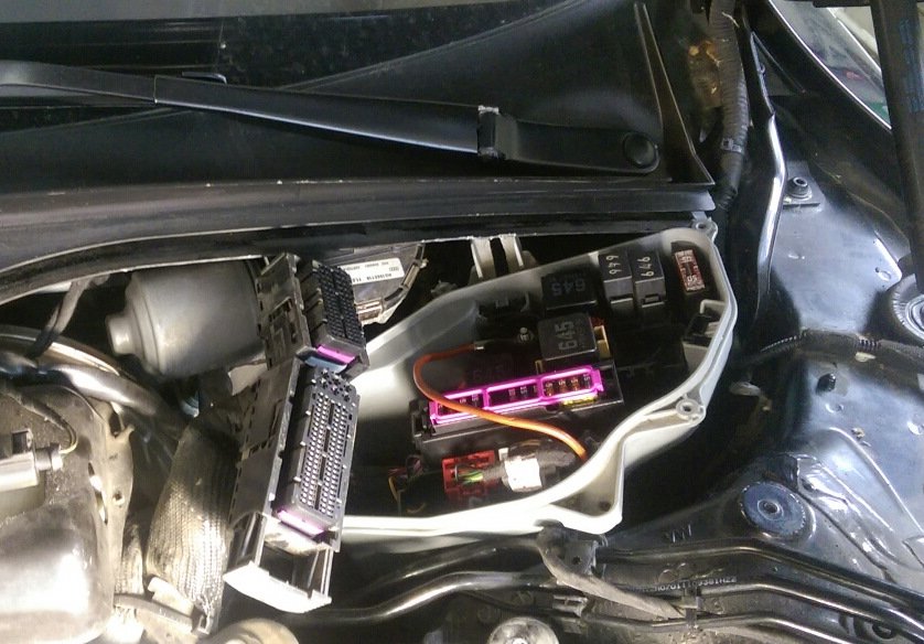
- Fuse and relay box in the plenum chamber on the driver’s side (E-Box) (under the washer reservoir). The cover of this
fuse box also serves as a bracket for the engine control unit. This fuse box is also called
E-Box; the fuses in it are indicated on the wiring diagram “SA”.

- Junction box and CAN bus node hub at the bottom of the left A-pillar.
- Fuse and relay box in the area of the onboard supply control unit . (under the dash panel in the driver’s side footwell). The fuses installed in it are indicated on the wiring diagram “SD”.
- Fuse box on the left side of the front panel. The fuses installed in it are indicated on the wiring diagram “SB”. These fuses can be accessed by the customer by removing the side cover on the front panel.
This material is intended to give the reader only a general idea of the structure of the electrical system, relays and fuse boxes in the Audi
A8 from 2010, the individual system elements are shown schematically. For the exact location of fuses and electrical wiring, please refer to the current service literature.
Fuse box in the left side of the dashboard

Diagram

Circuits protected
Fuse panel (B) | ||
| No. | A | Appointment |
| 1 | 5 | Headlight switch |
| 2 | 5 | Emergency start ( identification key ) |
| 3 | 7.5 | Control module (rear left door) |
| 5 | 15 | Sound signal |
| 6 | 7.5 | Interior lighting ( ceiling ) |
| 8 | 10/5 | Steering column grip, steering wheel heating, multi-steering wheel |
| 10 | 5 | Steering column adjustment |
| 11 | 7.5 | Control module ( driver’s door ) |
| 12 | 10 | Diagnostic connector , light / rain sensor |
| 14 | 25 | Steering column adjustment |
| 15 | 20 | Power steering, air conditioning compressor |
| 16 | 15 | Brake booster |
Fuse panel (C) | ||
| 1 | 30 | Heated front seats |
| 2 | 30 | Wiper |
| 3 | 30 | Front exterior lighting |
| 4 | 20 | Sunroof |
| 5 | 30 | Driver’s window regulator |
| 6 | 15 | Driver’s seat ( pneumatic ) |
| 7 | 20 | Panoramic sunroof |
| 8 | 35 | Dynamic steering |
| 9 | 30 | Front exterior lighting |
| 10 | 35 | Windshield washer, headlight washer |
| 11 | 30 | Rear left power window |
| 12 | 40 | Panoramic sunroof |
Fuse box in the right side of the dashboard
Photo

Diagram

Designation
| No. | A | Appointment |
| 1 | 5 | Anti-theft system |
| 2 | 15 | Transmission control module |
| 3 | 40 | Front climate control fan |
| 4 | 35 | Engine power |
| 5 | Spare | |
| 6 | 5 | Engine control module |
| 7 | 7.5 | Control module (front right door) |
| 8 | 30 | Front passenger window regulator |
| 9 | 10 | ESC control module |
| 10 | 25 | ESC control module |
| 11 | 30 | Rear right power window |
| 12 | 15 | Front passenger seat ( pneumatic ) |
Engine compartment fuse box
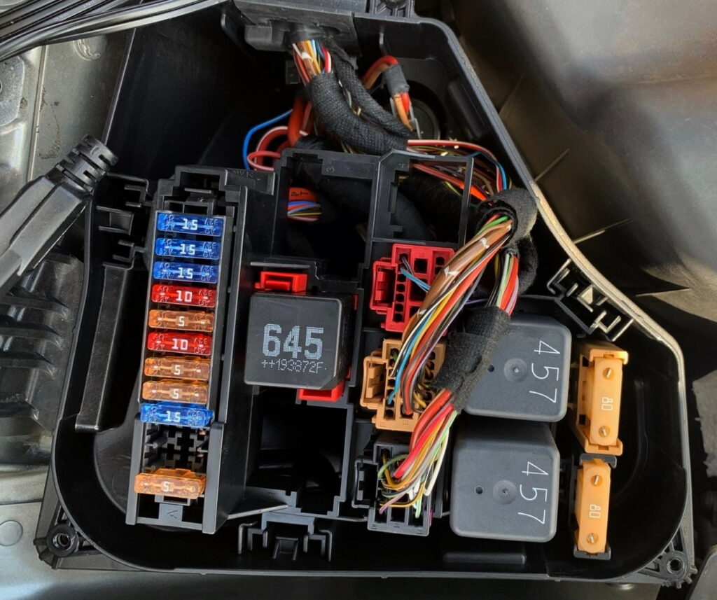
Diagram
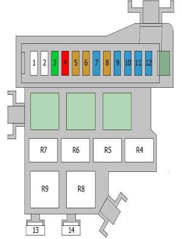
Appointment
| 1 | 5A Mass air flow meter |
| 2 | Empty |
| 3 | Empty |
| 4 | 15A Engine control unit |
| Engine control unit 2 | |
| 5 | 5A Cooling fan control unit |
| Fuel pump control unit | |
| Fan | |
| Gas pump relay | |
| 6 | 5A brake light switch |
| 7 | 10A Glow plug control unit |
| Electro-hydraulic left engine mounting bracket | |
| Transmission mount solenoids | |
| Transmission oil cooling valve | |
| 8 | 5A Oil level and temperature sensor |
| 9 | 10A Transmission mounting solenoids |
| Fuel pressure control valve | |
| Fuel dosing valve | |
| 10 | 15A Oxygen sensors |
| 11 | 15A Glow plug control unit |
| Right engine mount electrohydraulic solenoid | |
| Exhaust gas cooler valve | |
| Oil pressure control valve | |
| Cooling system bypass valve | |
| Special connector | |
| Transmission mount solenoids | |
| 12 | 15A Exhaust gas recirculation coolant pump |
| Coolant circulation pump | |
| 13 | 80A Glow plug |
| 14 | 50A Glow plug |
| R8 | Glow plug control unit |
| R9 | Glow plug control unit |
Luggage compartment fuse box
Location

Diagam
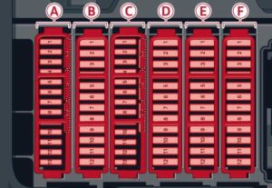
Protected components
Fuse panel (A) | ||
| No. | A | Appointment |
| 1 | 5 | Button , data logger , diagnostic connector , BCM – 1 , adaptive lighting system |
| 2 | 5 | Network gateway |
| 3 | 5 | Adaptive air suspension |
| 4 | 5 | |
| 5 | 5 | Steering column lever |
| 6 | 5 | Suspension control sensor |
| 7 | 5 | Seat belt pretensioners , airbag control unit |
| 8 | 5 | Heated washer nozzle , homelink system ( garage door opener ), night vision control module , sports differential , ionizer |
| 9 | 5 | Electromechanical parking brake control module |
| 10 | 5 | Rear seat heater, refrigerator , rearview mirror |
| 11 | 5 | Dynamic steering |
| 12 | 5 | Gear shift lever , ВСМ – 2 |
| 13 | 5 | Lane change assistant Audi side assist |
| 14 | 5 | Engine control module |
| 15 | 40 | Starter |
| 16 | 10/5 | Left headlight position sensor |
Fuse panel (B) | ||
| 1 | 25 | Left seat belt pretensioner |
| 2 | 25 | Right seat belt pretensioner |
| 3 | 5 | Starter diagnostics |
| 4 | 7.5 | DC / DC converter |
| 5 | 7.5 | Adaptive cruise control |
| 6 | 10 | Right headlight ( headlight with adaptive light ) |
| 7 | 5 | ESC control module |
| 8 | 5 | Sound actuator, AEM control unit |
| 9 | 10 | Adaptive cruise control |
| 10 | 5 | Transmission control module |
| 11 | 5 | Climate control sensors |
Fuse panel (C) | ||
| 1 | 5 | Electromechanical parking brake |
| 2 | 5 | Suspension control sensor |
| 3 | 7.5 | Control module (rear right door) |
| 4 | 5 | Smart modul tank |
| 5 | 15 | Front climate control unit |
| 6 | 10 | Rear climate control unit |
| 7 | 5 | Network gateway |
| 8 | 15 | Refrigerator |
| 9 | 5 | Interface for special functions |
| 10 | 5 | T The telephone adapter , the Bluetooth handset |
| 11 | 15 | AEM control module |
| 12 | 10 | Gear shift lever |
| 13 | 10 | External lighting |
| 14 | 20 | Rear exterior lighting |
| 15 | 25 | Fuel pump |
| 16 | 30 | Electromechanical parking brake |
Fuse panel (D) | ||
| 3 | 20 | Rear socket |
| 5 | 15 | Adaptive air suspension |
| 6 | 25 | Socket |
| 7 | 30 | Electromechanical parking brake |
| 8 | 25 | Rear seat heating |
| 9 | 20 | Rear exterior lighting |
| 10 | 20 | Rear climate control fan |
| 11 | 20 | Rear sun visor , door closer , trunk lock , keyless go / entry , fuel filler flap |
| 12 | 30 | Trunk lid control module |
Fuse panel (E) | ||
| 1 | 5 | Rear seat adjustment unit |
| 3 | 7.5 | Left rear seat ( pneumatic ) |
| 5 | 20 | Trailer hitch control module |
| 6 | 30 | Left rear seat |
| 7 | 30 | Right rear seat |
| 8 | 20 | Trailer hitch control module |
| 9 | 15 | Trailer hitch control module |
| 10 | 7.5 | Right rear seat ( pneumatic ) |
Fuse panel (F) | ||
| 1 | 30 | Radio receiver / sound amplifier |
| 2 | 30 | Amplifier |
| 3 | 10 | RSE (Rear Seat Entertainment) multimedia system, radio / sound amplifier |
| 5 | 5 | Auto dimming rearview mirror |
| 6 | 5 | DVD player |
| 7 | 5 | TV tuner |
| 8 | 7.5 | MMI unit/drives |
| 9 | 5 | Instrument cluster, analog clock |
| 10 | 5 | MMI display |
| 11 | 7.5 | Radio receiver |
| 12 | 5 | Rear view camera ( parking sensors ), top view |
Relays
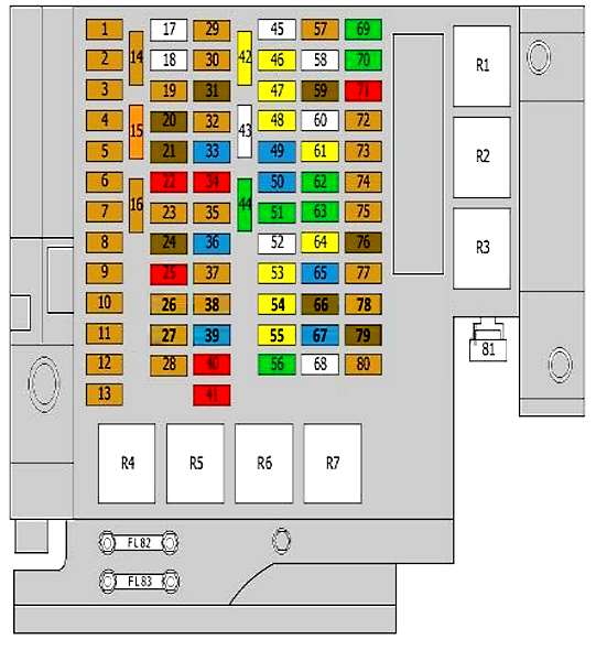
Assignment
- R1 – Adaptive suspension compressor relay
- R2 – Rear window heating
- R3 – Automatic anti-glare rear view mirror / Cooling fan relay
- R4 – Gasoline pump relay
- R5 – Engine starter relay
- R6 – Terminal 15, relay supply voltage
- R7 – Relay power socket
Additional protection elements can be placed nearby: 30A reducer heater, 10A reagent dosing system and reagent dosing system relay.
Additional Information
Video example of the location of the fuse boxes in the Audi A8 D4.
Check out our YouTube video for more on this topic. Don’t forget to subscribe!
Still trying to locate the Auxiliary engine coolant pump relay
I’m looking for the power steering control module fuse on the 2011 Audi a8 D4. Tell me where it is please.