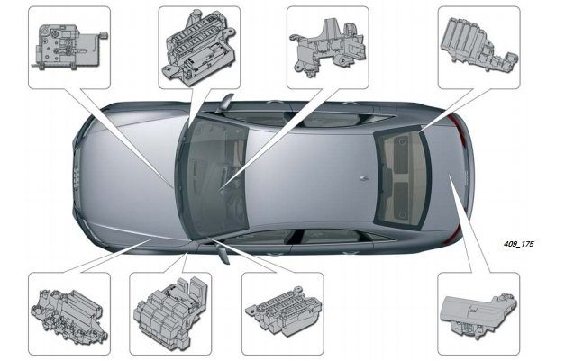
Audi A4 (B8) is the fourth generation of the Audi A4. Released in 2007, 2008, 2009, 2010, 2011, 2012, 2013, 2014 and 2015. This publication provides a description of the fuses and relays of the audi a4 b8 with diagrams and photographs of the boxes, as well as their locations. Let’s highlight the fuse responsible for the cigarette lighter.

The assignment of fuses and relays may differ from the one shown and depends on the year of manufacture and the level of electrical equipment of your vehicle.
Contents
Location
Passenger compartment
Left dashboard fuse box
To access the fuses, open the door and remove the cover. It will look something like this. An example of access is in our video at the end of the article.

Diagram

Designation for cars audi a4 b8 before 2010
| 1 | (5A) Power steering control module |
| 2 | (5A) Clutch pedal position sensor |
| 3 | (5A) Garage door remote control control module |
| 4 | (10A) Lane guidance control module |
| 5 | (5A) Heater air purity sensor |
| 6 | (5A) RH headlamp |
| 7 | (5A) LH headlamp |
| 8 | (5A) Onboard supply control unit |
| 9 | (5A) Interior rearview mirror with dimming |
| 10 | (5A) Gear shift control module |
| 11 | (5A) Heated windscreen washer nozzles |
| 12 | (5A) Air conditioning system |
| 13 | (5A) Coolant pump motor |
| 14 | (5A) Clutch pedal position sensor |
| 15 | (20A / 25A) Fuel pump control unit |
| 16 | (5A) Coolant pump motor |
| 17 | (30A) Onboard supply control unit |
| 18 | (10A) ABS control module |
| 19 | (25A) Horn |
| 20 | (30A) Door function control units |
| 21 | (30A) Windshield wiper motor |
| 22 | (25A) ABS control module |
| 23 | (15A) Door function control units |
| 24 | (5A) Rain and light sensor |
| 25 | – |
| 26 | – |
| 27 | (10A) Power seats |
| 28 | (35A) Power steering control module |
| 29 | (5A) Antenna amplifier |
| 30 | (35A) Onboard supply control unit |
| 31 | (20A) Onboard supply control unit |
| 32 | (30A) Onboard supply control unit |
| 33 | (20A) Sunroof control module |
| 34 | (30A) Onboard supply control unit |
| 35 | (20A) Sun shade |
| 36 | (5A) Anti-theft system |
Designation for cars audi a4 b8 from 2010
| F1 | (5A) Power steering control module |
| F2 | – |
| F3 | (5A) Garage door remote control control module |
| F4 | (10A) Lane guidance control module |
| F5 | (5A) Heater air purity sensor |
| F6 | (5A) RH headlamp |
| F7 | (5A) LH headlamp |
| F8 | (5A) onboard supply control unit |
| F9 | (5A) Cruise control module |
| F10 | (5A) Clutch pedal position sensor, clutch sensor control module, |
| F11 | (5A) Heated windscreen washer nozzles |
| F12 | (5A) Air conditioning system |
| F13 | (5A) Telephone connector |
| F14 | (5A) Hazard warning light button, airbag control module, seat occupied recognition, |
| F15 | (25A) ABS control module |
| F16 | (40A) Starter |
| F17 | (5A) Interior rearview mirror with dimming |
| F18 | (5A) Clutch pedal position sensor |
| F19 | (20A / 25A) Fuel pump control unit |
| F20 | (10A) Coolant pump motor |
| F21 | (15A/30A) |
| F22 | (10A) ABS control module |
| F23 | (25A) Horn |
| F24 | (30A) Door function control units |
| F25 | (30A) Windshield wiper motor |
| F26 | (25A) ABS control module |
| F27 | (15A) Door function control units |
| F28 | (5A) Rain and light sensor. |
| F29 | – |
| F30 | – |
| F31 | (10A) Power seats |
| F32 | (35A) Power steering control module |
| F33 | – |
| F34 | (35A) |
| F35 | (20A) |
| F36 | (30A) |
| F37 | (20A) Sunroof control module |
| F38 | (30A) |
| F39 | (20A) Sun shade |
| F40 | (5A) Anti-theft system |
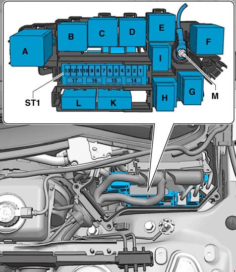
Right dashboard fuse board

Diagram

Assignment
| 1 | ST1 |
| 2 | |
| 3 | |
| 4 | |
| 5 | (5A) Steering column control module |
| 6 | (5A) ESP switch |
| 7 | (5A) Diagnostic connector (DLC) |
| 8 | (5A) CAN data bus, gateway control unit |
| 9 | (5A) Coolant heater |
| 10 | |
| 11 | |
| 12 | |
| 1 | (5A) Audio system – ST2 |
| 2 | (5A) Multifunction switch |
| 3 | (5A / 20A) |
| 4 | (5A) Instrument cluster control module |
| 5 | (5A) CAN data bus, gateway control unit |
| 6 | (5A) Keyless entry and start system |
| 7 | (5A) Headlamp switch |
| 8 | (40A) A / C / heater blower motor control module |
| 9 | (5A) Steering column lock control module |
| 10 | (10A) A / C control module |
| 11 | (10A) Diagnostic connector (DLC) |
| 12 | (5A) Steering column control module |
Additional box
6-pin rack-mount connection box

Located in the driver’s footwell, behind the side trim.
Relay and fuse box with used on-board network
Installation location of the relay / fuse box with a used on-board network under the panel on the driver’s side.
 Description
Engine compartment
Box in the center of the plenum chamber

Designation
- 40A, 60A – Fan control system 400 W. Fan control system 600 W
- 40A – Fan control 400 W
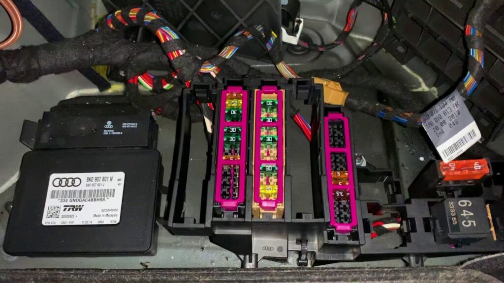
Switchgear fuse board
Photo for example

Diagram
Protected components
- A. Used automatic glow plug system (until 2011)
- A. Power Relay for Engine Components
- B. Starter relay (up to 2011)
- B. Starter relay 2
- C. Relay pump sec, air
- D. Power relay cl. 30 (until 2011)
- D. Motronic Power Relay
- E. Fuel relay pump
- E. Relay add. fuel pump
- E. Coolant recirculation relay after engine shutdown
- E. Relay add. pump system. cooling
- E. Gearbox cooling circuit relay
- E. Power relay for motor components 2
- F. not used
fuses for cars up to October 2011 release
| 1 | 15 A | Automatic transmission control unit. Mechatronic unit for dual clutch gearbox |
| 2 | 5 A | Engine oil level and temperature sensor |
| 3 | 5 A | Engine control unit. Air mass meter |
| 4 | 5a | Engine control unit |
| 5 | 10A, 15A, 20A | Air mass meter. Automatic glow plug control unit. Secondary air pump relay. Low power heating relay. High power heating relay. Solenoid valve for boost pressure limitation. Crankcase ventilation heating resistor. Solenoid valve 1 of the adsorber. Secondary air control valve. solenoid valve for the left electro-hydraulic engine support. solenoid valve for the right electro-hydraulic engine support. The valve of the system of changing the geometry of the intake manifold. Air filter bypass flap valve -. Fuel pressure control. Fuel metering valve. Secondary air control valve 2-. Exhaust gas recirculation cooler changeover valve. Oil pressure relief valve. Fuel system diagnostic pump |
| 6 | 15 A | Engine control unit |
| 7 | 10A, 15A | actuator 1 of the variable valve timing system. actuator 9 of the variable valve timing system. Solenoid valve for boost pressure limitation. Solenoid valve 1 of the adsorber – the solenoid valve of the left electro-hydraulic engine support. solenoid valve for the right electro-hydraulic engine support. Valve 1 of the variable valve timing system. Valve 2 of the variable valve timing system. Charge air recirculation valve. Fuel pressure control-. Fuel metering valve. Intake manifold flap valve -N316-. Valve 1 of the exhaust camshaft adjuster -. Valve 2 of the exhaust camshaft adjuster. Climatronic coolant shut-off valve. Oil pressure relief valve. Fuel system diagnostic pump. Inflatable air cooling pump |
| 8 | 10A, 5A, 20A | Exhaust gas recirculation cooler pump -V400-. Ignition coil 1 with output stage. Ignition coil 2 with output stage. Ignition coil 3 with output stage. Ignition coil 4 with output stage. Ignition coil 5 with output stage. Ignition coil 6 with output stage |
| 9 | 5A, 15A, 20A | Relay for additional fuel pump. Heating element for lambda probe 1 after catalytic converter. Heating element for lambda probe 2 after catalytic converter |
| 10 | 10A, 15A | Lambda probe heating element. Heating element for lambda probe 2. Heating element for lambda probe 1 after catalytic converter |
| 11 | 5 A | Radiator fan control unit. Radiator fan control unit 2 |
| 12 | 5 A | Air mass meter. Automatic gearbox control unit mechatronic for dual-clutch gearbox |
from October 2011
| 1 | 15 A | Automatic gearbox control unit – mechatronic for dual clutch gearbox |
| 2 | 5 A | Engine oil level and temperature sensor |
| 3 | 5 A | Engine control unit |
| 4 | 5 A | Engine control unit |
| 5 | 10A, 5A | Air mass meter. Fuel pressure control. Fuel metering valve |
| 6 | 15 A | Engine control unit – Injector 2 cylinders 1, 2, 3, 4 |
| 7 | actuator 1, 2, 3, 4, 5, 6, 7, 8 of the variable valve timing system. Solenoid valve for boost pressure limitation. Solenoid valve 1 of the adsorber solenoid valve of the left electro-hydraulic engine support. solenoid valve for the right electro-hydraulic engine support. Valve 1 of the variable valve timing system. Valve 2 of the variable valve timing system. Charge air recirculation valve. Fuel pressure control. | |
| 8 | 10A, 15A, 5A | NOx sensor 2. NOx sensor control unit 2 |
| 9 | 5 A | Voltage regulator. Engine control unit |
| 10 | 10A, 15A | Lambda probe heating element |
| 11 | 5 A | Radiator fan control unit |
| 12 | 5 A | Automatic transmission control unit |
| 13 | not used | |
| 14 | 5A, 20A | Engine Component Power Relay 2. Ignition Coil 1 with Output Stage. |
| 15 | 5 A | Power steering control unit |
| 16 | 15 A | Thermostat for the parametric engine cooling system. Automatic glow plug control unit |
| 17 | 15 A | Lambda probe heater after catalytic converter |
Luggage compartment
Fuse box is located behind the right side trim. Item descriptions may differ from those shown.
Diagram

For cars up to 2010
| A | Sedan: Not used |
| B | – |
| C | Sedan: Heated rear window relay |
| D | – |
| E | Accessory Power Connector Relay |
| 1 | (30A) Trunk lid control module |
| 2 | – |
| 3 | (30A) Trunk lid control module |
| 4 | (5A) Plug connector |
| 5 | – |
| 6 | – |
| 7 | – |
| 8 | – |
| 9 | – |
| 10 | – |
| 11 | – |
| 12 | – |
| 13 | (5A) Tire pressure monitor control module |
| 14 | (15A) Trailer control module |
| 15 | (20A) Trailer control module |
| 16 | (20A) Trailer control module |
| 17 | (5A) Electric parking brake control module |
| 18 | (15A) Suspension control module |
| 19 | (30A) Electric parking brake control module |
| 20 | (30A) comfort system |
| 21 | (35A) 4WD electronic control module |
| 22 | (30A) comfort system |
| 23 | (20A) comfort system |
| 24 | (5A) vehicle location management system |
| 25 | (15A / 30A) Accessory power connector |
| 26 | (15A) Heated seat control module |
| 27 | (7.5A) navigation system / radio |
| 28 | (30A) Audio system |
| 29 | (5A) Multifunction display control unit |
| 30 | (30A) Auxiliary heater control module |
| 31 | (30A) Electric parking brake control module |
| 32 | (30A) Heated seats |
| 33 | (30A) Door function control units |
| 34 | (5A) Auxiliary heater remote control receiver |
| 35 | (15A) Door function control units |
| 36 | (5A) Rear view camera control module |
| 37 | (15A) Accessory power connector |
| 38 | (15A) Accessory power connector |
| 39 | (15A) Accessory power connector |
| 40 | (15A) Cigar lighter |
| 41 | (5A) Self-parking control module |
| 42 | – |
| 43 | (5A) Distance control module (cruise control) |
| 44 | (15A) Rear window wiper motor |
| 45 | (5A) Electric parking brake control module |
| 46 | (5A) Lane change assist control unit |
| 47 | (5A) Heated seats |
| 48 | (5A) Hazard warning lights, airbag control module |
| 49 | – |
| 50 | – |
| 51 | (10A/15A/25A) |
| 52 | (10AL5A) Special vehicle equipment |
| 53 | (5A / 15A) Automotive special equipment |
| 54 | (10A) Special vehicle equipment |
| 55 | (5A / 20A) Special vehicle equipment |
| 56 | (10A) Special vehicle equipment |
| 57 | (10A) Accessory power connector |
| 58 | (10A) Special vehicle equipment |
| 59 | (10A) Special vehicle equipment |
| 60 | – |
| 61 | (40A) Heated rear window |
from 2010
| 1 | not used | |
| 2 | not used | |
| 3 | 15A. 25A | Alarm system control unit |
| 4 | 15 A | Alarm system control unit |
| 5 | 5A, 15A | Special signal control panel, Alarm system control unit |
| 6 | Control panel for special signals. Alarm system control unit, Tachograph control unit. Male connector, 3-pin. Alarm memory | |
| 7 | 20 A | Control unit for special vehicles |
| 8 | 10 A | Alarm memory |
| 9 | 10 A | 12V socket |
| 10 | 10 A | Walkie talkie dividing relay, walkie talkie relay |
| 11 | 10 A | Walkie talkie dividing relay, walkie talkie relay |
| 12 | not used | |
| 13 | 30 A | Rear lid control unit 2 – |
| 14 | 15 A | Trailer detection control unit |
| 15 | 20 A | Trailer detection control unit |
| 16 | 20 A | Trailer detection control unit |
| 17 | 5 A | AUTO HOLD button |
| 18 | 15 A | Control unit for electronic shock absorber adjustment |
| 19 | 30 A | Electromechanical parking brake control unit |
| 20 | 30 A | Convenience system central control unit |
| 21 | 35 A | All-wheel drive control unit |
| 22 | 30 A | Convenience system central control unit |
| 23 | 20 A | Convenience system central control unit |
| 24 | 5 A | Vehicle location system interface control unit |
| 25 | 30 A | Rear lid control unit |
| 26 | 15 A | Right front seat ventilation control unit |
| 27 | 40 A | Radio tape recorder. Phone transceiver – TV tuner. Mobile phone amplifier. Phone holder-. Male connector, 18-pin |
| 28 | 40 A | Voltage regulator |
| 29 | 30 A | Inverter with socket, 12V |
| 30 | 30 A | Additional heater control unit |
| 31 | 30 A | Electromechanical parking brake control unit |
| 32 | 30 A | Switch with adjustable rear left heated seat. Heated Rear Right Seat Switch with Adjustment |
| 33 | 30 A | Right doors |
| 34 | 5 A | Auxiliary heater receiver |
| 35 | 15 A | Right doors |
| 36 | 30 A | Additive dosing system control unit |
| 37 | 15 A | 12V socket |
| 38 | 15 A | 12V socket -. Inverter with socket, 12V – 230V |
| 39 | 15 A | 12V socket |
| 40 | 15 A | Cigarette lighter |
| 41 | not used | |
| 42 | 5 A | Plug connector, 2-pin, in the backrest of the driver’s seat. Plug connector, 2-pin, in the backrest of the driver’s seat |
| 43 | 7.5 A | Park assist control unit |
| 44 | 15 A | Rear window wiper motor |
| 45 | 5 A | Electromechanical parking brake button |
| 46 | 5 A | Lane change assist control unit 2 |
| 47 | 5 A | Switch with adjustable rear left heated seat |
| 48 | 5 A | Trailer detection control unit. All-wheel drive control unit. Voltage regulator. Electromechanical parking brake control unit |
| 49 | not used | |
| 50 | not used | |
| 51 | 20A, 30A | Digital audio system control unit. Radio cassette |
| 52 | 7.5A | Electronic information system control unit |
| 53 | 5A, 7.5A | Control unit for navigation system with CD drive. Radio tape recorder. Telephone transceiver -. TV tuner – Mobile phone amplifier. Phone holder-. Male connector, 18-pin |
| 54 | 5 A | Rear view camera control unit |
| 55 | 5 A | Mobile Phone Amplifier |
| 56 | not used | |
| 57 | not used | |
| 58 | not used | |
| 59 | not used | |
| 60 | not used | |
| 61 | 40 A | Heated rear window relay – Heated rear window |
The fuse number 40 at 15A is responsible for the cigarette lighter.
Additional Information
In this video you can see the locations of the main presented relay and fuse boxes.
Also, We have posted a video on our YouTube channel. Watch and subscribe.
2010 Audi a4 b8, Fog lights stay on when car is off. I tried to turn the fog lights off by starting the engine and turning the light switch, but the fog lights stayed on. I went for a drive, 5 minutes into the drive, the horn turned on without me pressing it, and stayed on until the fuse burned out. I also lost power steering right after the horn started. I have disconnected the battery for now. what could have gone wrong in the car? would anyone be able to assist me?
Hello did you find the problem ? My car is doing the same thing ! Thanks
Could be a short somewhere.
I’ve got a 2009 audi a4 went out in it yesterday got back into the car now the ignition lights won’t come on windows won’t go back up
I have a 2015 A4 Quattro. My passenger side headlight went out, so I switched it with the drivers side and it worked. When I put a testing light to it it lights up but the bulb still doesn’t.
May be shortage with ground & selector switch.
hi i am currently trying to replace relay 377 wiper control relay on my a4 b8 2009 saloon but cant find it would anyone be able to assist please
After driving through rain storm, my Audi A4 B8 crank but not start. Mechanic complete all relevant checks including firing, cleaning injectors, check fuel pump & filter, high pressure fuel pump, run diagnostics (no error codes on car), still the same problem, car won’t start. Anybody with the same situation? Please any help.
Hi, does anyone know where the stop/start chip is located on 2018 audiA4 .I need to replace .Thanks
BCM could be the problem. I had a similar issue. The BCM has some water intrusion which caused the board to short circuit.
Run a scan and see what codes are revealed. Mine were all BCM related.
Ordered a new BCM, had dealer reprogram. All is well
Is there any fuse that powerup up with reverse Gear?
Since I want t power the reverse camera with reverse light.
Or what cable can be used to connect for rever power?
You should be able to connect your positive wire for the camera to the positive wire of the reverse light and use the ground wire as well or create your own ground wire if you want.
Hi my heated wing mirrors are no longer working would anyone know if it’s a fuse and if so where would it be located A4 2013 model
does the Audi A4 2010 have a fuse for the washer motor, and where would it be?
Same problem with finding fuse and relay for this in my 2011
Same issue. My trunk lid, fuel filler cap, windscreen washer have all given up at same time. Can’t find fuses for any of these on my 2009 A4
Does anyone know where I can find the right fuse for the power steering, now I can barely steer the car. Or if anyone has experience what else could be wrong?
The error code is:
B200049 – Ctrl. module faulty
static
U140A00 – Terminal 30 Open circuit
Audi A4 – 2013
I have the same problem with my A4 2015. In about -25°C in Oslo area recently I first drove a short trip of about 15 min. Then, after a few minutes stop, I got red steering wheel and message “do not drive”, when starting the engine. I have checked the 5A fuse in pos. 15 at the Swichgear fuse board. That was my last hope, and my next step is to remove the steering gear to try to find the error.
These are the errors, (the latter one was removed upon clearing errors):
5258756 – Steering
C10AC 07 [137] – Mechanical Failure
[Blockieren der Lenkung]
7343439 – Motor for Electric Power Steering
C10AE 13 [137] – Open Circuit
[Phasenunterbrechung mit Hilfe des GatedCounters erkannt (kritischer Fehler)]
7343624 – Motor for Electric Power Steering
C10AE 1B [008] – Resistance Too High
[Relais-Fritting fehlgeschlagen]
I have understood that this is a common failure on Audi electro mechanical steering gears, and a have read terrifying stories about huge costs related to repair.
If you have progress in research on this, please let me know. I will keep you informed on any progress here.
I solved the problem by replacing the complete steering rack. After a lot searching the net I understood that the rack, and most probably its control unit, may be damaged by operating in strong cold when the battery is not close to 100% charged.
I found a used (not reconditioned) rack at Ragn-Sells for NOK 3500 and replaced it myself. Happy to avoid an extra 0 at the bill and a lot of waiting for some workshop to order from Germany and do the job.
Before removing the old rack I measured exactly position of the wheels in straight forward position. I did this by measuring from a marked point on the curved suspension member and out to a small notch I made on the caliper, with 0.5 mm accuracy. Thus, I could obtain the same wheel alignment without need of a costly trip to workshop.
Final calibration (by Ross-Tech VCDS); first Steering wheel G85 Basic Settings and then Steering rack Basic settings for resetting end stops. (The Ross-Tech procedure for steering wheel rotation is missing an important point: When engine is running, press brake pedal and engage a gear before turning the wheel.)
Now I am just waiting nervously for the next red lamp and buzzing sound, giving me new challenges in the garage.
2009 Audi A4 B8 had similar problem with the passenger side head light. It lost all power to xenon, DRL, and side markers. After replacing everything, I ended up finding out it was the harness. So de-pinned and replaced and works great now. Hope this helps
Alguien sabe por qué el ventilador no enciende llegando a las 90