The Audi Q7 is a full-size crossover that is currently in production. This material provides a description of all fuse and relay bloxes of the Audi Q7, as well as their locations and diagrams for cars produced in 2005, 2006, 2007, 2008, 2009, 2010, 2011, 2012, 2013, 2014 and 2015 (1st generation). Let’s show the fuse responsible for the cigarette lighter.

The assignment of fuses and relays may differ from that shown, depending on the year of manufacture and the level of electrical equipment.
Contents
Location
Layout

Assignment
- Front panel fuse holder (left) -SB-;
- Front panel fuse box (right) -SC-;
- Relay and fuse box in the center of the front panel;
- Onboard supply control unit – J519-;
- Luggage compartment relay and fuse box on the right – SF-;
- Relay and fuse box under the driver’s seat -SD-;
- Relay and fuse box of the switching unit;

Passenger compartment
Front left fuse box
Photo for example

Diagram

Protected components
| No. | A | Function / component |
| A | – | Not used |
| B | 10 | Main fuse for bodywork -S245- |
| C | – | Not used |
| D | – | Not used |
| Fuse box 1 | ||
| 1 | 5 | Before June 2010: Not used From June 2010: Voltage stabilizer -J532- |
| 2 | 5 | Before June 2010: Not used From June 2010: Relay for dimming rearview mirror -J910- |
| 3 | 7.5 | Before June 2010: Not used From June 2010: Information electronics control unit 1 -J794- |
| 4 | 5 | Up to June 2010: Tire pressure monitor control unit -J502- |
| 5 | 20 | Additional heater control unit -J364- |
| 6 | 10 | LHD: Driver seat lumbar support adjustment switch -E176- |
| 6 | 10 | RHD: Front passenger seat lumbar support adjustment switch -E177- |
| 7 | 35 | LHD: Driver door control unit -J386- Driver’s door window regulator motor -V147- Rear left door control unit -J388- Rear left door window regulator motor -V26- |
| 7 | 35 | RHD: Front passenger door control unit -J387- Rear right door window regulator motor -V27- Front passenger door window regulator motor -V148- |
| 8 | 15 | LHD: Driver’s door control unit -J386- Rear left door control unit -J388- (up to May 2008) |
| 8 | 15 | RHD: Front passenger door control unit -J387- Rear right door control unit -J389- |
| 9 | 5 | Up to May 2008: Power management control unit -J644- From June 2010: Tire pressure monitor control unit -J502- |
| 10 | 30 | LHD: Entry and start monitoring system control unit -J518- Access and start authorization switch-E415- |
| 10 | 5 | RHD: Media player in position 1 -R118- (up to June 2009) Media player in position 2 -R119- (up to June 2009) CD changer -R41- (up to May 2010) Mini disc player -R153- (up to June 2009) Video recorder and DVD player -R129- (up to June 2009) DVD player -R7- (June 2009 to May 2010) Connector for external audio sources -R199- (November 2006 to June 2009) |
| 11 | 10 | LHD: Steering column control unit -J527- |
| 11 | 10 | RHD: Climatronic operating and display unit, rear -E265- Control unit for fresh air blower, rear -J391- |
| 12 | 5 | LHD: Interior monitor sensor -G273- Autonomous siren -H12- |
| 12 | 5 | RHD: Convenience system central control unit -J393- |
| Fuse box 2 | ||
| 1 | – | Not used |
| 2 | – | Not used |
| 3 | 15 | Before June 2009: Not used From June 2009: Left front seat ventilation control unit -J800- |
| 4 | 30 | Wiper motor control unit -J400- Wiper motor -V- |
| 5 | 5 | Rain and light sensor -G397- |
| 6 | 25 | Dual tone horn relay -J4- High frequency horn -H2- Low frequency horn -H7- |
| 7 | 30 | LHD: Onboard supply control unit -J519- |
| 7 | 25 | RHD; from June 2010: 12 V socket 3 -U19- 12 V socket 4 -U20- |
| 8 | 25 | LHD: Onboard supply control unit -J519- |
| 8 | 20 | RHD: Cigarette lighter -U1- |
| 9 | 25 | LHD: Onboard supply control unit -J519- |
| 9 | 25 | RHD: 12 V socket -U5- 12 V socket 2 -U18- |
| 10 | 10 | LHD: Control unit in dash panel insert -J285- (up to May 2010) Data bus diagnostic interface -J533- Display panel in dash panel insert -Y24- (up to May 2010) |
| 10 | 10 | RHD: Climatronic control unit -J255- Fresh air blower control unit -J126- |
| 11 | 30 | Headlight washer relay -J39- |
| 12 | 10 | Connector 16-pin -T16-, diagnostic connector |
| Fuse box 3 | ||
| 1 | 10 | Left headlight |
| 2 | 5 | Distance control control unit -J428- Distance control (ADR) sensor heater -Z47- |
| 3 | 5 | Direct view Japan Display unit -J145- Display panel button -E506- Coolant shut-off valve relay -J541- 2) Heater coolant shut- off valve -N279- 2) |
| 4 | 10 | Lane Departure Warning Control unit for lane departure warning system -J759- Heated windscreen for lane departure warning system -Z67- |
| 5 | 10 5 1) | LHD: Signal unit control unit -J616- (up to June 2009) Control panel for special signals -E507- (up to June 2009) Connection kit for multimedia system (9WM) (from November 2007) |
| 5 | 5 | RHD: Multimedia Connection Kit (9WM) (from November 2007) |
| 6 | 5 | LHD: Steering column control unit -J527- Entry and start authorization control unit -J518- Light switch -E1- Convenience system central control unit -J393- Trailer detection control unit -J345- Tire pressure monitor control unit -J502 – (7K6) (since June 2008) |
| 6 | 5 | RHD: Heated rear left seat -Z10- Heated backrest, rear left -Z11- Heated rear right seat -Z12- Heated backrest, rear right -Z13- |
| 7 | 5 | Engine oil level and temperature sender -G266- |
| 8 | 5 | Connector 16-pin -T16-, diagnostic connector |
| 9 | 5 | Auto dimming rearview mirror -Y7- |
| 10 | 5 | Garage door opener control unit -J530- Garage door opener control unit -E284- |
| 11 | 5 | Data bus diagnostic interface -J533- |
| 11 | 5 | Airbag control unit -J234- |
| 12 | 5 | LHD: Headlight range control adjuster -E102- Left headlight range control servomotor -V48- Right headlight range range control motor -V49- |
| 12 | 5 | RHD: Air quality sender -G238- Climatronic operating and display unit, rear compartment -E265- Climatronic control unit -J255- |
1) From November 2007
2) Only for vehicles with 6-cylinder engine generation 2
LHD – Left-hand drive
vehicles RHD – Right-hand drive vehicles
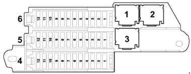
Front right fuse box
Location

Diagram

Purpose of elements
| No. | A | Function / component |
| A | 5 | Fuse for structure-borne noise control unit -S348- |
| B | 5 | From June 2008: Refrigerated compartment fuse -S340- |
| C | – | Not used |
| D | – | Not used |
| Fuse box 1 | ||
| 1 | 20 | Heated rear left seat -Z10- Heated backrest, rear left -Z11- Heated rear right seat -Z12- Heated backrest, rear right -Z13- |
| 2 | 10 | Up to May 2010: Automatic gearbox control unit -J217- (0AT) |
| 2 | 5 | Automatic gearbox control unit -J217- (09D) (up to May 2010) Mobile phone amplifier -R86- (from June 2010) Card reader control unit -J676- (from June 2010) Telephone holder -R126- ( since June 2010) |
| 3 | 30 | Heated front left seat -Z45- Heated front right seat -Z46- |
| 3 | 15 | RHD; from June 2009: Heated front right seat control unit -J799- |
| 4 | 20 | ABS control unit -J104- |
| 5 | 15 | LHD: Front passenger door control unit -J387- Rear right door control unit -J389- (up to May 2008) |
| 5 | 15 | RHD: Driver door control unit -J386- Rear left door control unit -J388- |
| 6 | 25 | LHD: 12 V socket 3 -U19- 12 V socket 4 -U20- |
| 6 | 25 | RHD; before May 2010: 12 V socket 3 -U19- 12 V socket 4 -U20- |
| 6 | 30 | RHD; from June 2010: Onboard supply control unit -J519- |
| 7 | 10 | LHD: Front passenger seat lumbar support adjustment switch -E177- RHD: Driver seat lumbar adjustment switch -E176- |
| 8 | 20 | LHD: Cigarette lighter -U1- |
| 8 | 25 | RHD: Onboard supply control unit -J519- |
| 9 | 25 | LHD: 12 V socket -U5- 12 V socket 2 -U18- |
| 9 | 25 | RHD: Onboard supply control unit -J519- |
| 10 | 10 | LHD: Climatronic control unit -J255- Fresh air blower control unit -J126- |
| 10 | 10 | RHD: Up to June 2010: Control unit in dash panel insert -J285- From June 2010: Data bus diagnostic interface -J533- |
| 11 | 5 | Up to June 2010: Brake light switch -F- (up to May 2008) Brake pedal switch -F47- (up to May 2008) ABS control unit -J104- (up to May 2008) |
| 11 | 15 | From June 2010: Refrigerated compartment -J698- |
| 12 | 15 | Onboard supply control unit 2 -J520- |
| Fuse box 2 | ||
| 1 | 10 | Right headlight |
| 2 | 5 | Ground clearance control unit -J197- |
| 3 | 5 | Mobile phone installation kit (9ZD) |
| 4 | 5 | Lane change assist control unit -J769- Control unit 2 for lane change assist -J770- |
| 5 | 5 | Brake light deactivation relay -J508- Clutch pedal switch -F36- (up to June 2009) |
| 6 | 5 20 | 5A: Automatic gearbox control unit -J217- 20A: Automatic gearbox control unit -J217- (09D) |
| 7 | 5 | ABS control unit -J104- |
| 8 | 5 | Multifunction switch -F125- Tiptronic switch -F189- Selector lever sensor control unit -J587- |
| 9 | 5 | Parking aid control unit -J446- Outdoor camera control unit -J928- (from June 2012; LHD) |
| 10 | 5 | LHD: Airbag control unit -J234- RHD: Data bus diagnostic interface -J533- |
| 11 | 5 | LHD: Heated rear left seat adjustment switch -E128- Heated rear right seat adjustment switch -E129- |
| 11 | 5 | RHD: Steering column control unit -J527- Entry and start authorization control unit -J518- Light switch -E1- Convenience system central control unit -J393- Trailer detection control unit -J345- |
| 12 | 5 | LHD: Air quality sender -G238- Climatronic operating and display unit, rear compartment -E265- Climatronic control unit -J255- |
| 12 | 5 | RHD: Headlight range control adjuster -E102- Left headlight range control servomotor -V48- Right headlight range range control motor -V49- |
| Fuse box 3 | ||
| 1 | 15 | Up to May 2007: Rear wiper motor -V12- From June 2008: Cooled compartment -J698- |
| 1 | 10 | From June 2010: Control unit in dash panel insert -J285- |
| 2 | 5 | Up to June 2010: Left injector heating resistor -Z20- Right-hand injector heating resistor -Z21- From June 2010: Reversing camera control unit -J772- |
| 3 | 30 | LHD: Not used RHD: Onboard supply control unit -J519- |
| 3 | 5 | From June 2010: DVD player -R7- 1) CD changer -R41- 1) |
| 4 | 5 | From June 2009: Display for dash panel insert -J685- |
| 5 | 5 | Up to June 2009: Sender / receiver unit for telephone -R36- Up to May 2010: Telephone holder -R126- Card reader control unit -J676- |
| 5 | 10 15 | From June 2010: Automatic gearbox control unit -J217- |
| 6 | 15 | Front operating unit control unit -J523- Aerial amplifier -R24- |
| 6 | 7.5 | Up to June 2009: Control unit for dash panel, display and information output -J523- Up to May 2010: Information electronics control unit 1 -J794- |
| 6 | 30 | From June 2010: Gearbox hydraulic pump relay -J510- 1 ) Additional hydraulic pump control unit -J922- 1) |
| 7 | 20 | Sliding sunroof control unit -J245- |
| 8 | 20 | Rear sliding sunroof control unit -J392- |
| 9 | 20 | Roof blind control unit -J394- |
| 10 | 5 | LHD: Media player in position 1 -R118- (up to June 2009) Media player in position 2 -R119- (up to June 2009) CD changer -R41- (up to May 2010) DVD player -R7- (up to May 2010) Mini disc player -R153- (up to June 2009) |
| 10 | 30 | RHD: Entry and start monitoring system control unit -J518- Entry and start authorization switch -E415- |
| 11 | 35 | LHD: Front passenger side window regulator motor -V148- Rear right door window regulator motor -V27- |
| 11 | 35 | RHD: Driver door control unit -J386- Driver’s door window regulator motor -V147- Rear left door control unit -J388- Rear left door window regulator motor -V26- |
| 12 | 10 | LHD: Climatronic operating and display unit, rear -E265- Control unit for fresh air blower, rear -J391- |
| 12 | 10 | RHD: Steering column control unit -J527- |
For the operation of the cigarette lighter and additional sockets (USB), fuses 6, 8 and 9 are responsible.
1) Only for cars with start / stop system
LHD – cars with left hand drive
RHD – cars with right hand drive
Relay box
It is located in the center, under the front panel.

Diagram

Designation
| No. | A | Function / component |
| B | – | Not used |
| C | 30 | Trailer detector control unit -J345- (USA only) Brake booster (USA only) |
| D | 30 | Seat and steering column adjustment control unit with memory function -J136- Front passenger seat adjustment control unit with memory function -J521- |
| E | – | Not used |
| F | – | Not used |
| G | – | Not used |
| 1b | 40 | Supply fan -V2- |
| 2b | 40 | ABS control unit -J104- |
| 3b | 40 | Fresh air blower for rear compartment -V80- |
| 4b | 40 | Heated rear window -Z1- |
| 5b | 15 | From June 2007: Rear wiper motor -V12- |
| 6b | 5 | From June 2007: Heated resistor for left washer nozzle -Z20- Heated resistor for right washer nozzle -Z21- |
| A1 | – | Not used |
| B1 | – | Not used |
| C1 | – | Not used |
| D1 | – | Not used |
| Relay | ||
| 1 | Ground clearance control compressor relay -J403- | |
| 2.1 | Power relay, cl. 75x -J694- | |
| 2.2 | Dual tone horn relay -J4- | |
| 3 | Headlight washer relay -J39- | |
| 4 | Brake light deactivation relay -J508- | |
| 5 | Not used | |
| 6 | Heated rear window relay -J9- | |
| 7.1 | V6 TDI / FSI, V8 MPI / FSI, V12 TDI: Coolant circulation relay after off. engine -J151- (V6 FSI from June 2009) | |
| 7.1 | Coolant shut-off valve relay -J541- (only for vehicles with 2nd generation 6-cylinder diesel engine) | |
| 7.2 | From June 2010: Relay for dimming rearview mirror -J910- | |
| 8 | Gearbox hydraulic pump relay -J510- (from June 2010, only for vehicles with 8-speed automatic gearbox) | |
| 1a | Not used | |
| 2a | Not used | |
| 3a | Not used | |
Fuse and relay box
Located under the driver’s seat
Diagram

Description of the circuit
| No. | A | Function / component |
| 2 | – | Battery cut-off igniter -N253- |
| B | 40 | Ground clearance control fuse -S110- |
| B1 | 30 | From June 2010: Fuse 1 (30) -S204- |
| B2 | 5 | From June 2008: Fuse for vehicle location system -S347- |
| B3 | – | Not used |
| B4 | 30 | From June 2010: Fuse 2 (30) -S205- |
| SD1 | 150 | Fuse 1 on fuse holder D -SD1- |
| SD2 | 125 | Up to May 2006: Fuse 2 on fuse holder D -SD2- |
| SD2 | 150 | From June 2006: Fuse 2 on fuse holder D -SD2- |
| SD3 | 50 | Fuse 3 on fuse holder D -SD3- |
| SD4 | 60 | Fuse 4 on fuse holder D -SD4- |
| SD5 | 125 | Fuse 5 on fuse holder D -SD5- |
| Relay | ||
| 1 | Terminal 15 voltage supply relay -J329- | |
Luggage compartment
Fuse and relay box

Diagram
Protected components
| No. | A | Function / component |
| Fuse box 6 | ||
| 1 | 15 | Up to May 2010: Signaling unit control unit -J616- From June 2010: Multimedia system control unit -J650- |
| 2 | 30 | Reducing agent dosing system control unit -J880- |
| 3 | 15 | Up to May 2010: Ground clearance control unit -J197- |
| 3 | 5 | From June 2012: Switch for reducing agent reservoir -F502- |
| 4 | 5 | From June 2009 to May 2010: Reversing camera control unit -J772- Reversing camera -R189- |
| 5 | 5 | Parking aid control unit -J446- |
| 6 | 15 | Convenience system central control unit 2 -J773- |
| 7 | 15 | Convenience system central control unit 2 -J773- |
| 8 | 5 | Radio receiver for auxiliary heater -R64- |
| 9 | 20 | 12 V socket 5 -U26- |
| 10 | 20 | Convenience system central control unit -J393- |
| 11 | 15 | Keyless entry antenna reader -J723- |
| 12 | 30 | Convenience system central control unit -J393- |
| Fuse box 5 | ||
| 1 | 15 | Signaling unit control unit -J616- |
| 2 | 5 | Special control panel signals -E507- |
| 3 | 15 | Radio isolation relay, radio relay -J84- Radio -R8- |
| 4 | 15 | Radio isolation relay, radio relay -J84- Radio -R8- |
| 5 | 5 | Radio -R- |
| 5 | 15 | From June 2010: Signaling unit control unit -J616- |
| 6 | 5 | TV tuner -R78- From June 2009: Not used |
| 7 | 5 | CD navigation system control unit -J401- From June 2009: Not used |
| 8 | 30 | Digital sound system control unit -J525- From June 2009: Not used |
| 9 | 5 | Digital radio -R147-, From June 2009: Not used |
| 10 | 30 | Digital sound system control unit 2 -J787-, From June 2009: Not used |
| 11 | 5 | Reversing camera control unit -J772- Reversing camera -R189- From June 2009: Not used |
| 12 | – | Not used |
| Fuse box 4 | ||
| 1 | 5 | From June 2009 to May 2010: Radio -R- |
| 1 | 7.5 30 | From June 2010: Digital sound system control unit -J525- |
| 2 | 5 | From June 2009: TV tuner -R78- From June 2011: Digital TV tuner -R171- |
| 3 | 30 | From June 2009: Digital sound system control unit -J525- |
| 4 | 30 | From June 2009: Digital sound system control unit 2 -J787- |
| 5 | 15 | Rear Seat Infotainment (9WP, 9WK) (November 2007 to May 2010) Multimedia system control unit -J650- (up to May 2010) From June 2010: The ride height control control unit -J197- |
| 6 | 20 | Convenience system central control unit -J393- |
| 7 | 30 | Boot lid control unit -J605- Motor for boot lid control unit -V375- |
| 8 | 30 | Boot lid control unit 2 -J756- Motor for boot lid control unit 2 -V376- |
| 9 | 15 | Trailer detection control unit -J345- |
| 10 | 15 20 1) | Trailer detection control unit -J345- |
| 11 | 15 20 1) | Trailer detection control unit -J345- |
| 12 | 30 25 1) | Trailer detection control unit -J345- Swing- out ball head motor -V317- |
| Relay | ||
| 1 | Not used | |
| 2 | Not used | |
| 3 | Connector 6-pin -T6am- for rear seat infotainment system | |
1) Since June 2007
Engine compartment
Fuse and relay box

For gasoline engines

Designation
| No. | A | Function / component |
| 1 | 40 60 | Radiator fan -V7- |
| 2 | 50 | Secondary air pump motor -V101- |
| 3 | – | Not used |
| 4 | 40 60 | Radiator fan 2 -V177- |
| 5 | 50 | Secondary air pump motor 2 -V189- |
| 6 | – | Not used |
| 7 | 30 20 4) | Ignition coils |
| 8 | 5 | Radiator fan control unit -J293- Radiator fan control unit 2 -J671- |
| 9 | 15 | Engine control unit -J623- Injectors |
| 10 | 10 | High pressure sensor -G65- 1) 2) 3) recirculation pump coolant -V50- 1) thermostat from the engine cooling system electronic control -F265- 1) I relay pumping coolant system after engine shutdown -J151- 1) valve 1 valve timing control system -N205- 1) 2) 3) valve 2 phase timing regulation system -N208- 1) 3) intake manifold flap valve -N316- 1) valve control system 1 phase timing of exhaust valves -N318- 1) 2) The valve control system 2 exhaust camshaft timing -N319- 1) Intake manifold flap valve 2 -N403- 1) Charge air cooling pump -V188- 3) |
| 11 | 5 | Engine control unit -J623- Air mass meter -G70- 2) |
| 12 | 5 | Crankcase ventilation heater resistor -N79- |
| 13 | 15 | Air mass meter -G70- 1) Air mass meter 2 -G246- 1) Solenoid valve 1 for activated charcoal filter -N80- 1) 2) Secondary air control valve -N112- 1) 3) Fuel metering valve -N290- 1) 2) Intake manifold flap valve -N316- 2) 3) Secondary air supply valve 2 -N320- 1) 3) Fuel metering valve 2 -N402- 1) Oil pressure regulating valve -N428- 3) Coolant pump after engine shutdown -V51- 3) Fuel system diagnostic pump -V144- 1) 2) 3) Crankcase ventilation shut-off valve -N548- 3) |
| 14 | 15 | Lambda probe -G39- Lambda probe 2 -G108- |
| 15 | 15 | Lambda probe after catalytic converter -G130- Lambda probe 2 after catalytic converter -G131- |
| 16 | 40 | Fuel pump control unit -J538- |
| 17 | 5 | Engine control unit -J623- |
| 18 | 15 | Vacuum pump for brake system -V192- 1) 2) |
| Relay | ||
| A1 | Up to June 2009: Starter relay -J53- From June 2009: Relay for voltage supply for engine electronics -J757- | |
| A2 | Up to June 2009: Starter relay 2 -J695- From June 2009: Motronic supply relay -J271- | |
| A3 | Up to June 2009: Relay for voltage supply for engine electronics -J757- From June 2009: Not used | |
| A4 | BAR: Secondary air pump relay -J299- (+ CJTC, CJTB, CJWB, CNAA, CJWC, CTWA, CTWB, CJWE from June 2009) | |
| A5 | Up to June 2009: Brake servo relay -J569- From June 2009: Starter motor relay -J53- | |
| A6 | Before June 2009: Relay for pumping coolant after off. engine -J151- From June 2009: Starter relay 2 -J695- | |
| B1 | Not used | |
| B2 | From June 2009: Not used | |
| B3 | Up to June 2009: Fuel pump relay -J17- From June 2009: Not used | |
| B4 | From June 2009: Not used | |
| B5 | Up to June 2009: Fuel cooling pump relay -J445- From June 2009: Not used | |
| B6 | Not used | |
| C1 | Up to June 2009: Circulation pump relay -J160- From June 2009: BAR: Circulation pump relay -J160- BHK, BHL: Brake servo relay -J569- CJTC, CJTB, CJWB, CNAA, CJWC, CTWA, CTWB, CJWE: Relay for auxiliary coolant pump -J496- | |
| C2 | Motronic supply relay -J271- Not used | |
For diesel engines

Assignment
| No. | A | Function / component | |
| 1 | 60 | Radiator fan control unit -J293- Radiator fan -V7- | |
| 2 | 80 | Glow plug control unit -J179- | |
| 3 | 40 | Heating element for auxiliary air heater -Z35- (400 W) 4) 11) 13) | |
| 4 | 40 1) 60 2) | Radiator fan control unit 2 -J671- Radiator fan 2 -V177- | |
| 5 | 80 60 13) 15) | Glow time control unit 2 -J703- 3) 5) 6) 10) Relay for 3rd heating stage -J959- 13) 15) | |
| 6 | 80 60 13) 15) | Heating element for auxiliary air heater -Z35- (2 x 400 W) 4) 11) | |
| 7 | 15 | Thermostat for parametric engine cooling -F265- 9) 13) Glow plug control unit -J179- Throttle valve -J338- 4) 5) 8) 11) Low heating output relay -J359- 4) 11) 13) High heating output relay -J360- 4) 11) 13) Turbocharger 1 control unit -J724- 7) Turbocharger 2 control unit -J725- 6) Bypass intercooler flap control unit -J865- 4) 11) Exhaust gas recirculation valve -N18- 7) Changeover valve exhaust gas recirculation cooler -N345- Exhaust gas recirculation cooler changeover valve 2 -N381- 4) 11) Electrohydraulic engine support solenoid valve -N398- 9) 13) Oil pressure regulating valve -N428- 3) 4) 9) 10) 11) 13) Cylinder head coolant valve -N489- 9) 10) 13) Intake manifold flap motor -V157 – 6) 7) Intake manifold flap motor 2 -V275- 7) | |
| 8 | 5 | Radiator fan control unit -J293- Radiator fan control unit 2 -J671- | |
| 9 | 15 | Engine control unit -J623- Engine control unit 2 -J624- 3) 5) 6) 10) | |
| 10 | 10 | Fuel pressure regulator -N276- Fuel metering valve -N290- Fuel metering valve 2 -N402- 5) Fuel pressure regulating valve 2 -N484- 5) | |
| 11 | 15 10 9) 11) | Lambda probe -G39- Lambda probe 2 -G108- 3) 5) 6) 10) Lambda probe heater -Z19- Lambda probe 2 heater -Z28- 3) 5) 6) 10) | |
| 12 | 10 5 4) 14) | Fuel cooling pump relay -J445- 3) 5) 6) NOx sensor control unit -J583- 4) 13) NOx sensor 2 control unit -J881- 4) 11) 13) Coolant coolant pump -V166- 3 ) 6) Pump for exhaust gas recirculation cooler -V400- 3) 5) 10) Not used 7) 8) 9) Diesel particulate filter -G784- 13) | |
| 13 | 10 15 4) 5) | High pressure sender -G65- Relay for circulating coolant after engine shutdown -J151- Relay for fuel cooling pump -J445- 4) 7) 8) Glow plug control unit 2 -J703- 3) 5) 6) 10) Recirculation cooler changeover valve 2 Exhaust gas -N381- 5) Coolant pump after engine shutdown -V50- Coolant pump after engine shutdown -V51- 4) 8) 10) 11) Coolant pump -V166- 4) 7) 8) Intake manifold flap motor 2 -V275- 6) Pump for exhaust gas recirculation cooler -V400- 4) 8) | |
| 14 | 5 | Air mass meter -G70- Air mass meter 2 -G246- 3) 5) 6) 10) | |
| 15 | 5 | Engine control unit -J623- Engine control unit 2 -J624- 3) 5) 6) 10) | |
| 16 | 20 25 | Fuel supply pump -G6- Fuel pump control unit -J538- 9) 10) 13) | |
| 17 | 20 | Fuel pump -G23- 5) 6) 7) 8) | |
| 17 | 10 | Pressure sender for reducing agent dosing system -G686- 4) Additive pump -V437- 4) Additive heating element -Z103- 4) | |
| 17 | 5 | Engine control unit -J623- 9) 10) 11) 13) Engine control unit 2 -J624- 10) | |
| 18 | 7.5 | Crankcase ventilation heating resistor -N79- 3) 5) 6) 10) Crankcase ventilation heating resistor 2 -N483- 3) 5) 10) | |
| 18 | 20 | Relay for additional fuel pump -J832- 4) 8) Additional fuel pump -V393- 4) 8) | |
| 18 | 10 5 12) | Pressure sender for reducing agent dosing system -G686- 11) 13) Additive pump -V437- 11) 13) Heating element for additive pump -Z103- 11) 13) | |
| Relay | |||
| A1 | Glow plug control unit -J179- | ||
| A2 | Up to June 2009, V12: Starter motor relay -J53- From June 2009: Terminal 30 voltage supply relay -J317- | ||
| A3 | CCGA, CCFA, CCFC, V12: Glow time control unit 2 -J703- (CCFA, CCFC from June 2009) | ||
| A4 | Up to June 2009, V12: Starter relay 2 -J695- From June 2009; CCMA, CATA: Relay for additional fuel pump -J832- | ||
| A5 | Up to June 2009: Not used From June 2009: Starter relay -J53- | ||
| A6 | Up to June 2009: Relay for additional fuel pump -J832- From June 2009: Relay for starter 2 -J695- | ||
| B1 | CCMA, CATA, CLZB, CNRB: Low heat output relay -J359- (CLZB, CNRB from June 2009) | ||
| B2 | Not used | ||
| B3 | Up to June 2009: Fuel pump relay -J17- From June 2009; CLZB, CNRB: Relay for 3rd heating stage -J959- | ||
| B4 | CCMA, CATA, CLZB, CNRB: High heat output relay -J360- (CLZB, CNRB from June 2009) | ||
| B5 | Up to June 2009, V12: Fuel cooling pump relay -J445- From June 2009; CCFA: Additional heater fuel pump relay -J749- | ||
| B6 | CCGA, V12: Relay for auxiliary coolant pump -J496- | ||
| C1 | Up to June 2009, V12: Relay for additional heater fuel pump -J749- From June 2009; CCMA, CATA, CCFA: Fuel cooling pump relay -J445- | ||
| C2 | Up to June 2009, V12: Terminal 30 voltage supply relay -J317- From June 2009; CCFA: Fuel pump relay -J17- | ||
Socket for starting from an external power source

Splitter 2 for terminal 30 -TV22- / Socket for starting from external power supply -U6-
Check out our YouTube video for more on this topic. Don’t forget to subscribe!
Any questions left, ask them in the comments.
I have audi Q7 2007 with air suspension faulty not working. On the relay there is no power at terminal 30 when activated manually the pump is running but the car is not going up
My 2015 Q7 with 7 prong trailer plug (it’s actually it’s 4 prong) has no power coming to it. Removed the factory install receiver for the plug, no power coming to it? Any idea what my problem nay be? Thanks
I have a 2014 Audi Q7, 3.0T. My vehicle has the memory system where you can program the seat and steering wheel to remember my setting when you enter or leave the vehicle. My tilt steering was working when I used the knob to push it in and out BUT it was not working when I tried raising it up and down. I took my vehicle to the Audi dealership in New Jersey and I asked them to look at it and they told me that I had to replace the WHOLE steering system. When I got back my vehicle the steering column was not working at all. I dont know what the tech did to my steering column that it stopped working anymore. I was charged the service fee but I don’t know if they scanned or checked the fuses in the front panel, but not i am without my tilt steering and it sucks
Yes, Audi ‘Stealers’ don’t do repairs/diagnostics on this fixable issue as they want to replace the entire assembly, which is expensive and profitable for them. Honestly, don’t ever take your used Audi back to a dealership unless you just really like the overpriced hospitality there; the dealer shops exist to print money.
If you go look up the issue you’re having online, then you’ll find out there’s a way to DIY resolve your issue with the steering column. A lot of owners have also found post-dealer visit that an Audi tech pulled a fuse while they had it in shop to make it appear like the system has failed completely to the owner of car, and that is likely to be the case with yours too. Suggest you read the owner’s manual on the electric steering column controls/adjustments, as well.
It’s been awhile since read threads on this topic, but do believe the steering column resolution requires you to have a full access VAGCOM type scan tool, such as Ross-Tech VCDS, etc., in order to run the internal diagnostics and test protocols to reset/relearn the limits on the steering column movement vectors, but definitely do your research first on this issue before buying anything, although if you do DIY, then the VCDS scan tool allows you to do everything on this car, and it’s affordable too.
Check your steering column fuses to see if the dealer has pulled one or two of them and is pulling a fast one on you, and then go use the internet to find existing threads and online videos for resolving your steering column issue.