Volkswagen Transporter T5 belongs to the class of cargo and passenger vehicles. It was produced with minivan, van and pickup bodies with both diesel and gasoline engines. Produced in 2003, 2004, 2005, 2006, 2007, 2008, 2009, 2010, 2011, 2012, 2013 and 2014. From 2015 to the present, the sixth generation (T6) is in production. In our material you will find a designation of the purpose of fuses and relays in the Volkswagen T5 transporter with detailed boxes diagrams and their photographs. We will show the location of all control units and highlight the fuse responsible for the cigarette lighter for T5 and T6.

The number of elements in the boxes may differ from the one presented and depends on the year of manufacture (the car was restyled in 2010) and the level of its electrical equipment.
Contents
Location of control units
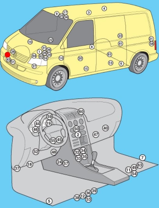
Designation
| 1 | ABS electronic control unit |
| 2 | Air conditioning control unit – in the heater control panel |
| 3 | Air conditioning control unit (rear) – in the heater control panel |
| 4 | Antenna unit – if available |
| 5 | Side impact sensor, driver’s side |
| 6 | Side impact sensor, rear left |
| 7 | Side impact sensor, passenger side |
| 8 | Side impact sensor, rear right |
| 9 | Anti-theft control unit |
| 10 | Anti-theft alarm horn – intake system resonator |
| 11 | Audio Output Amplifier – Under Front Right Seat – If Equipped |
| 12 | Additional battery 1 – under the front left seat – if equipped |
| 13 | Extra Battery 2 (RV) – in the kitchen cabinet |
| 14 | Additional heater control unit (Air Top 3500) – under the body bottom, on the right – if available |
| 15 | Additional heater control unit (Thermo Tor) – under the body bottom, on the left – if any |
| 16 | Accumulator battery |
| 17 | Camping equipment control unit (RV) |
| 18 | Diagnostic connector (DLC) |
| 19 | Diagnostic unit – dashboard |
| 20 | Driver’s door control unit |
| 21 | Rear left door electrical control unit (with power sliding door) – LH pillar |
| 22 | Passenger door electrical control unit |
| 23 | Rear Right Door Wiring Control Unit (Power Sliding Door) – Right Pillar |
| 24 | ESP stability control unit (includes acceleration sensor, lateral movement sensor) |
| 25 | Roof lift control unit (RV) |
| 26 | ECM – near engine fuse / relay box 1 |
| 27 | Cooling Fan Motor Control Module 1 – Suspension (Front Left) |
| 28 | Cooling fan motor control unit 2 – in the cooling fan motor 2 – if installed |
| 29 | Fuse / relay box, engine compartment 1 |
| 30 | Fuse / relay box, engine compartment 2 |
| 31 | Fuse / relay box, engine compartment Z |
| 32 | Fuse / Relay Box, Instrument Panel 1 – Center of Instrument Panel |
| 33 | Fuse / relay box 2, dash – under dash fuse / relay box 1 |
| 34 | Fuse / Relay Box, Instrument Panel 3 – Behind the Fuse / Relay Box, Instrument Panel 1/2 |
| 35 | Fuse / Relay Box, Instrument Cluster 4 – Behind the Fuse / Relay Box, Instrument Cluster 1/2 |
| 36 | Fuse / Relay Box, Left Seat – Under Seat |
| 37 | Additional fuse 1 (differential lock switch, rear 10A) – left front pillar |
| 38 | Additional fuse 2 (additional heater 30A) – under the left seat |
| 39 | Additional fuse 3 (door electronics control unit, left rear 40A) – under the left seat (some models) |
| 40 | Heater blower motor resistor 1 – near the rear heater blower motor |
| 41 | Heater blower motor resistor 2 – near the rear heater blower motor – if equipped |
| 42 | Beep 1 |
| 43 | Sound signal 2 – if available |
| 44 | Immobilizer Control Unit – Instrument Cluster |
| 45 | Immobilizer ring antenna – near the ignition switch |
| 46 | Instrument Cluster Control Unit – Instrument Panel |
| 47 | Telephone control unit – behind the glove box |
| 48 | Multifunction control unit 1 – functions: Automatic transmission (automatic transmission), charging system (with additional battery), cruise control, door / bonnet switch contact recognition, electrical load control, power windows, fuel pump, headlight washers, rear mirror heater door views, rear window defogger, hazard warning lights, windshield defroster, horn, direction indicators, instrument cluster illumination, interior lamps, automatic wipers, reversing lights, starter, sunroof, light switch, windshield washer, wiper windshield |
| 49 | Multifunction control unit 2 – functions: Anti-theft system, central locking, power door mirrors, power sliding door, power windows, sunroof |
| 50 | Navigation control unit – in navigation display |
| 51 | Ambient temperature sensor |
| 52 | Parking system control unit |
| 53 | Driver’s seat heating control unit |
| 54 | Heated passenger seat control unit |
| 55 | Steering Wheel Position Sensor – If Equipped |
| 56 | Sunroof electric control unit |
| 57 | SRS electronic control unit |
| 58 | Rear door open / close drive control unit – left “D” pillar – if equipped |
| 59 | Traffic information control unit – under the dash |
| 60 | Traffic information control unit (alternative position) – under the dashboard |
| 61 | Transfer case control unit (with 4WD) – rear final drive |
| 62 | Electronic gearbox control unit (automatic transmission) – near the engine control unit |
| 63 | Voice synthesizer – under the front right seat – if equipped |
| 64 | Vehicle speed sensor – gearbox (some models) |
Passenger compartment
Main box
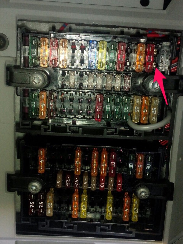
Photo for example
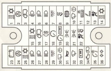
Diagram
Appointment
| 1 | (25A / 30A) Heater, air conditioner, terminal 15 power relay |
| 2 | (5A) Steering wheel position sensor |
| 3 | (10A) Multifunction control module 1 (onboard supply) |
| 4 | (10A) Headlight range control (5A) Lane change assist |
| 5 | (15A) Left headlight bulb |
| 6 | (15A) Left headlight bulb |
| 7 | (15A) Multifunction control module 1 (interior lamp or vehicle electrical system) |
| 8 | (5A) Diagnostic connector (DLC) (15 / 20A) sliding roof and door control unit, tailgate |
| 9 | (15A) Brake light switch (brake pedal position sensor) (30A) Onboard supply control unit |
| 10 | (10A) Windshield wiper, rear window wiper |
| 11 | (5A) License plate lamp |
| 12 | (15A) Cigarette lighter (5 / 30A) Light switch |
| 13 | (5 / 10A) SRS electronic control unit |
| 14 | (30A) Auxiliary heater heater, air conditioning (25A) Headlamp switch |
| 15 | (7.5) Air conditioning (fan switch and relay) |
| 16 | (5A) Multifunction control module |
| 17 | (5A) Rear fog lamps, instrument cluster |
| 18 | (5A) Instrument cluster control module |
| 19 | (5A) Audio system, instrument cluster control unit, multifunction control unit 1, navigation system, special vehicle equipment |
| 20 | (5A) Front left-hand, left-hand brake light, tail-light-left, or differential lock |
| 21 | (5A) Front light-right, right-hand brake light, tail-light-right, or starter relay, engine control module |
| 22 | (7.5 / 10A) Passenger airbag deactivation indicator, diagnostic connector (DLC), instrument cluster control unit |
| 23 | (5 / 30A) Starter relay (some models with manual transmission) |
| 24 | (5A) Steering wheel position sensor |
| 25 | (7.5A) Air conditioner (fans) |
| 26 | (30A) Headlamp switch |
| 27 | (15A) Right headlight bulb |
| 28 | (15A) Headlamp high beam indicator, right headlamp |
| 29 | (10A) Tailgate signal relay |
| 30 | (10A) Heated windscreen washer nozzles, rear window wiper motor |
| 31 | (30A) Multifunction control module 1 (horn) |
| 32 | (25 / 30A) Multifunction control module 1 (windscreen wiper motor) |
| 33 | (15A) Audio system, navigation system, traffic information control module |
| 34 | (25A) Automatic transmission control system, fuse / relay box, engine compartment 1 |
| 35 | (5A) Instrument cluster illumination |
| 36 | (25A) Multifunction control module 1 (direction indicators) |
According to the diagram, fuse number 12 is responsible for the cigarette lighter.
Lower section diagram
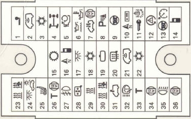
Protected components
| 1 | (25A) Trailer electrical connector (15A) 10-pin connector |
| 2 | (5A) Anti-theft system |
| 3 | (5A) Heater air conditioner auxiliary fan, left and right (10 / 15A) Optional equipment |
| 4 | (10A) Transfer case control module (differential) |
| 5 | (10A) Accessory connector or 6-pin connector |
| 6 | (5A) Engine oil condition sensor (level, temperature) |
| 7 | (10A) Roof fan (30A) Anti-theft alarm |
| 8 | (5A) Parking system |
| 9 | (5A) Steering column control module (cruise control) |
| 10 | (30A) Audio system (10A) Headlight range control, instrument lighting level |
| 11 | (20A) Anti-theft alarm horn, multifunction control module 2, electric sliding door, tailgate opener control module (15A) Walkie-talkie, anti-theft system |
| 12 | (5A) LH headlight (10A) Brake light off relay (30A) Onboard power supply control |
| 13 | (5A) Cruise control main switch, multifunction steering wheel control |
| 14 | (5A) Telephone, RH headlight (30A) Onboard power supply management |
| 15 | (5A) Automatic transmission or Telephone and voice control |
| 16 | (5A) Audio system navigation system, telephone (7.5A) TV tuner |
| 17 | (7.5A) Multifunction control module (interior lamp, dimmable mirror) |
| 18 | (5A) Air conditioner (some models) |
| 19 | (5A) Auto dimming interior rearview mirror |
| 20 | (10A) Multifunction control module 1 (door mirror heater) |
| 21 | (5A) Anti-theft system or rain sensor |
| 22 | (5A) Air conditioning or pressure sensor |
| 23 | (5A) Auxiliary heater and accessories |
| 24 | (7.5A) Interior lamps |
| 25 | (15A / 25A) Heated seats |
| 26 | (10A) Tachograph (if equipped) |
| 27 | (15A) Fog lamps or power supply relay |
| 28 | (5A) Rearview mirror adjustment switch, door mirror heaters |
| 29 | (25A) Auxiliary heater |
| 30 | (5A) Auxiliary heater |
| 31 | (25A) Hatch (5A) Onboard charger |
| 32 | (20A) Headlamp washers and its relay |
| 33 | (5A) Tachograph (if equipped) |
| 34 | (15A) Auxiliary power supply connector 3 (rear) (5A) Multifunction steering wheel control module |
| 35 | (10A) Multifunction control unit 1 (reversing light (s), with automatic transmission) (20A) Onboard supply control unit |
| 36 | (5A) Camping equipment control unit, special vehicle equipment |
Relay box behind main fuse box
Type 1

Assignment
| 1 | – |
| 2 | Relay 1 auxiliary heater |
| 3 | A / C blower motor relay, rear |
| 4 | Relay for auxiliary ignition circuits |
| 5 | – 06/03: Rotating beacon relay (special purpose vehicle) |
| 6 | Brake light cut-off relay |
| 7 | Headlight washer pump relay |
| 8 | A / C / heater auxiliary pump relay |
| F1 | – |
| F2 | (30A) Door control module (driver), door control module (passenger) |
| F3 | (40A) Heated rear window |
Type 2

Description
| 1 | A / C blower motor relay, rear (some models) |
| 2 | Steering column electronics control unit |
| 3 | Steering column electronics control unit |
| 4 | Roof fan relay 1 |
| 5 | Differential lock control unit |
| 6 | 06/03: Tailgate signal relay |
| F1 | (15A) Siren (special purpose vehicle) |
| F2 | (10A) Siren (special purpose vehicle) |
| F3 | (10A) Rotating beacon (special vehicle) |
| F4 | (40A) Rear left door control module |
| F5 | (40A) 01/04: Rear right door control module |
| F6 | (5A) 01/04: Voice synthesizer (if available) |
Box under the driver’s seat
Type 1

Designation
| 1 | Relay – divider in the charging system (with additional battery) |
| 2 | – |
| 3 | Relay – divider in the charging system (with additional battery) |
| 4 | Special vehicle equipment |
| 5 | Special vehicle equipment |
| F1 | (5A) Camping equipment control box |
| F2 | (10A) Accessory Power Socket 1 (Front), Refrigerator (RV) |
| F3 | (5A) Fresh water pump (camper) |
| F4 | (10A) Interior lamps, local lighting (commercial vehicle) |
| F5 | (30A) Bodywork power connector control module (commercial vehicle) |
| F6 | (40A) Roof lift control module (commercial vehicle) |
| F7 | (5A) Antenna unit |
| F8 | (25A) Additional heater |
| F9 | (30A) Heater air conditioner blower motor (automatic temperature control) |
| F10 | – |
| F11 | – |
| F12 | – |
| F13 | (40A) Right rear door control module |
| F14 | (80A) Additional storage battery |
Type 2

Appointment
| 1 | – |
| 2 | Relay divider in the charging system (with additional battery) |
| 3 | Special vehicle equipment |
| 4 | Special vehicle equipment |
| 5 | Special vehicle equipment |
| F1 | (15А) Accessory power connector (s) |
| F2 | (15А) Accessory power connector (s) |
| F3 | (15А) Accessory power connector (s) |
| F4 | (15А) Refrigerator (van), special vehicle equipment |
| F5 | (5A) Antenna unit |
| F6 | (25A) Additional heater |
| F7 | (30A) Air conditioner / heater blower motor (automatic temperature control) |
| F8 | – |
| F9 | – |
| F10 | – |
| F11 | (40A) Right rear door control module |
| F12 | (80A) Additional storage battery |
Type 3

Designation
- 5A – 10-pin connector / 6-pin connector
- 3A – 10-pin connector
- 5 / 15A – 10-pin connector or emergency data logger
- 15A – 10-pin connector
- 5A – 10-pin connector
- 25A – 6-pin connector
- 15/30 – 12V socket, voltage converter
- 20 / 25A – Heater (heater) control unit
- 25 / 30A – Supply fan
- 15 / 30A – Climate control
- 15A – Cigarette lighter
- 5A – 10-pin connector / 6-pin connector
- Local relay
- Local relay
- Local relay
- 30A – On-board charger
- 30A – Roof hydraulics control unit
- 10A – Lighting plafonds
- 10A – Cooled compartment
- 5A – Water pump
- 5A – Camper equipment control panel
- 15A – 12V socket
- 15A – 12V socket
- 10A – Roof fan or 12V socket
- 15A – Trailer recognition control unit
- 20A – Trailer recognition control unit
- 20A – Trailer recognition control unit
- 7.5A – Trailer recognition control unit
- Reserve
- 5A – Voice amplifier control unit
- Reserve
- Reserve
- 15A – Lumbar support for the driver’s seat
- 40A – Right sliding door control unit
- 80A – Control unit for charging the second battery
- 40A – Left sliding door control unit
- 40A – Supply fan
- 6-pin connector
- Reserve
This block contains fuses responsible for the cigarette lighter (number SF11) and additional sockets.
Engine compartment
Fuse mounting box
Box photo

Example circuit

Assignment
| 1 | (5A) Cooling fan (s) motor (s) |
| 2 | (5A) Coolant pump relay |
| 3 | (15A) Air conditioning (5A) Crankcase ventilation resistor |
| 4 | (30A) Anti-lock braking system (ABS) or Voltage stabilizer, Stereo, Radio |
| 5 | (15A) Automatic transmission |
| 6 | (30A) Anti-lock braking system (ABS) |
| 7 | (5A) Cooling fan motor control unit 1 (7.5A) Washer pump |
| 8 | (15A) Engine management |
| 9 | (5A) Engine management, main ignition circuit relay |
| 10 | (5A) Engine management (15A) Charge or exhaust valve |
| 11 | (5A) Power steering control unit (30A) Headlamp switch and headlight relay |
| 12 | (5A) Engine management (10A) Fuel pressure regulator |
| 13 | (10A) Engine management (10A) Xenon in the left headlight |
| 14 | (5A) Engine management or fuel pump relay |
| 15 | (10A) Reversing light switch |
| 16 | (5A) Engine management or brake light switch, air flow meter |
| 17 | (5A) Anti-lock braking system (ABS) |
| 18 | (5A) Power steering |
| 19 | (5A) Brake light switch (brake pedal position sensor), clutch pedal position sensor |
| 20 | (5A) Engine management |
| 21 | (5A) Exhaust gas recirculation valve |
| 22 | (10A) Engine management (injectors) |
| 23 | (25A) Automatic transmission (10A) Xenon headlight right |
| 24 | (5A) Automatic transmission |
| 25 | (25A) Engine management, Ignition |
| 26 | (25A) Engine management (5A) LH headlight |
| 27 | (5A) Coolant pump relay |
| 28 | (15A) High tone signal |
| 29 | (10A) Vehicle speed sensor (5A) Right headlight |
| 30 | (15 / 20A) A / C / heater auxiliary pump relay, fuel pump, fuel pump relay |
| 31 | (15A) Engine management (lambda probe) |
| 32 | (30A) Engine management (ignition) (5A) Fuel pump relay |
| 33 | (5A) Coolant pump relay engine management, glow plug relay |
| 34 | (10A) Cooling fan motor control unit (5A) Bot network control unit |
| 35 | (10A) Engine management (15A) Fuel level regulator |
| 36 | (25A / 30A) Starter relay (5A) Data bus interface |
High power fuse box
Located next to the assembly and connected to the battery.

Designation
| 1 | (175 / 225A) Generator |
| 2 | (125A) Battery power distribution, auxiliary ignition relay, driver’s door control unit, passenger door control unit, rear window defroster, terminal X relay, separate fuses |
| 3 | (50A / 100A) Charging system (with additional battery), rear left door electrical control unit (some models), rear right door electrical control unit (some models), relay – divider in the charging system (with additional battery) |
| 4 | (125A) Battery power distribution (70A) Positive connection in the engine compartment wiring harness |
| 5 | (50A) Battery power distribution (some models), separate fuses |
| 6 | (60A) Glow plug relay (50A) Exhaust air pump motor |
| 7 | (70/80 / 100A) Cooling fan (s) motor |
| 8 | (40/50 / 100A) Cooling fan (s) motor, separate fuses |
| 9 | (100A) Battery power distribution, ignition switch |
| 10 | – |
Relay box
Also located next to the fuse box.

Type 1

Appointment
| 1 | Air conditioning electronic control unit (manual temperature control) |
| 2 | Fuel pump relay 2 |
| 3 | Outlet air pump relay |
| 4 | Relay for main ignition circuits |
| 5 | Fuel pump relay 1 |
| 6 | A / C compressor electromagnetic clutch relay (automatic temperature control) |
| 7 | Automatic transmission control system relay |
| 8 | Power steering control unit |
| 9 | Coolant pump relay |
Type 2

Designation
| 1 | Air conditioning electronic control unit (manual temperature control) |
| 2 | Fuel pump relay 2 |
| 3 | Outlet air pump relay |
| 4 | Relay for main ignition circuits |
| 5 | Fuel pump relay 1 |
| 6 | A / C compressor electromagnetic clutch relay (automatic temperature control) |
| 7 | – |
| 8 | Coolant pump relay |
| 9 | Starter relay – if equipped |
Fuses in the Transporter T6
In the sixth generation, the main fuse box is located under the glove compartment.
Photo for example

Fuse number 49 at 15A is responsible for the cigarette lighter. Outlined in red in the figure.
We have posted a video on our YouTube channel. Watch and subscribe.
If you have something to add – write in the comments.
Hi, is this diagram OK for the 57 plate bnz engine (2.5 t5)?
Also, we noticed a lot of auxiliary heater fuses are missing or wrong type compared to the diagram… should we follow the diagram or trust the fuses (auxiliary heater seems to be playing up.)
Thanks in advance.
I can’t seem to see the ECM relay designated anywhere, is it described as something else on here.
Thanks
Hi did you find ecm relay as I have problems with mine 2015 transporter.?
Where is the glowplug relay situated on the kombi 1.9tdi T5?
58 plate T5..My wipers only work for a short time then may start again a little later but not always until vehicle is switched off for a while…already changed wiper motor, would this issue be relay if so where is it or could it be the stalk
Hi Kevin,
Did you ever find out what it was as I have the same issue! like you I have replaced the motor and have half pulled the dash out trying to find relays etc. Starting to loose the will to live.
Anything you found out would be greatly welcomed.
Thank Andy.
My indicator repeaters on both front wings don’t work. How are they wired and are they fuse indepentantly from the front and rear flashers which work ok.
I have a transporter T5 2009 model and has missed the connection flip for fuse no 30 – and need to take the fuse box out for getting it back in place. How do I demount the fuse box? Do I need to demount the whole dashboard? Thank you very much for your advice.
Hi,
Does a 2006 ( pre facelift ) have high capacity fuse box under battery ,,
Thanks
Sean
Evening guys, been looking at your diagrams, have a 2015 t5.1 with drivers side drl out, changed bulbs, no joy, no power at the bulb holder, and can’t see a listing for it, incase there is a dedicated fuse. Thank you
Sveiki turiu broblemu su valytuvo pertraukima padetimi.
ko tik nedariau; pakeiciau varikliuka, pakeiciau valalytuvu valdymo rankeneles, pakeiciau mažaja valytuvo rele, valdymo bloke, nerandu kur stovi didžioji rele, po akumu nera