The Volkswagen Scirocco is a compact hatchback that has been produced in three generations since 1974. Our material will be useful to owners of the 3rd generation produced in 2008, 2009, 2010, 2011, 2012, 2013, 2014, 2015, 2016 and 2017. We will show the location of the fuse and relay boxes, their diagrams and designations, which are exclusive to the Volkswagen Scirocco 3G.
The design of the fuse boxes may differ from the one shown and depends on the year of manufacture and equipment of your vehicle.
Engine compartment
Layout
Fuse box
Located at the end of the panel behind the protective cover.
Diagram
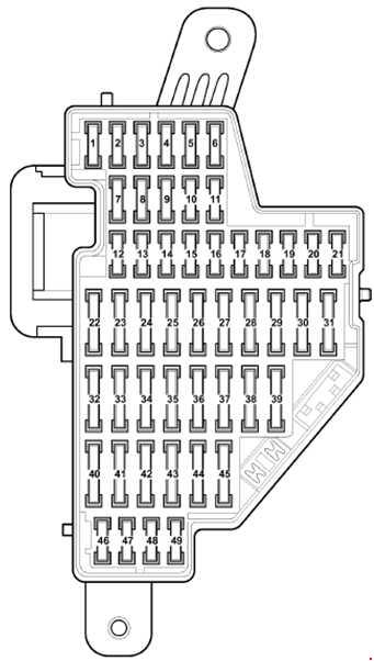
Assignment
Consumer | Number (Ampere Current) |
ABS | 2 (10), 4 (5) |
Tilt sensor | 17 (5) |
Airbags | 3 (5) |
Brake light switch | 2 (10) |
Deffirming adjustment system | 35 (20) |
ESP | 2 (10), 4 (5) |
Front windows | 23 (30) |
Fan | 22 (40), 40 (40) |
Heated rear window | 25 (25) |
Rear wiper | 41 (15) |
Interior security system | 17 (5) |
Instrument cluster | 2 (10) |
Fuel pump | 27 (15) |
Lumbar support | 34 (15) |
Headlights corrector | 1 (10) |
SunRoof | 33 (30) |
Rain sensor | 13 (10) |
Washer nozzles | 4 (5) |
Headlight cleaner | 36 (20) |
Seat heating | 37 (30) |
Cigarette lighter and sockets | 42 (20) |
central locking | 12 (10) |
The fuse number 42, 20A, is responsible for the cigarette lighter.
Relay box
Diagram
Allocation
- 1 – 2010-2017: Relay carrier on top of onboard supply control unit
- A 20A – 2008-2009: Driver seat adjustment thermal fuse 1
- B 20A – 2010-2017: Driver seat adjustment thermal fuse 1
Engine compartment
Layout
Photo for example of one of the options
Type 1
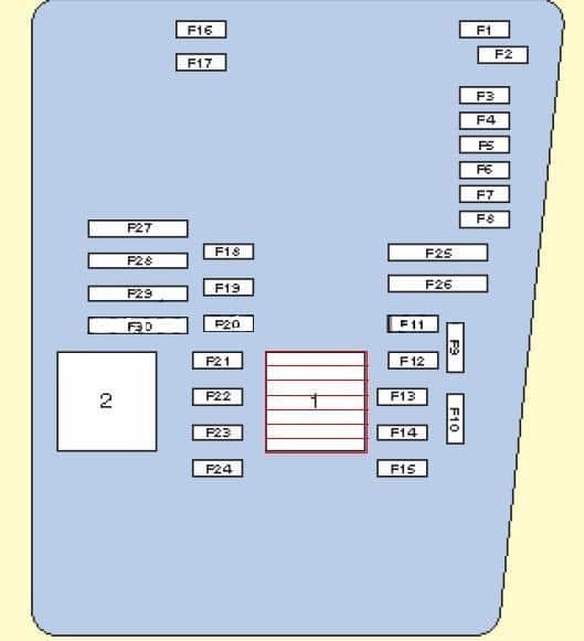
Designation
F1 | – | – |
F2 | 30A | Mechatronic unit for dual clutch gearbox |
F3 | 5A | Battery monitor control unit (with start/stop) Onboard supply control unit |
F4 | 20A/ 30A | ABS control unit |
F5 | 15A | Mechatronic unit for dual clutch gearbox |
F6 | 5A | Control unit in dash panel insert (without start/stop) Steering column electronics control unit |
F7 | 40A | 2008: Mechatronic unit for dual clutch gearbox 2009-2017: Terminal 15 voltage supply relay 2 |
F8 | 15A /25A | Voltage stabiliser (with start/stop) Display unit for front information display and operating unit control unit with control unit 1 for information electronics (without start/stop) Radio (2008-2014) |
F9 | 5A | Emergency call module control unit and communication unit (without start/stop) |
F10 | 10A/ 5A | Engine control unit Main relay |
F11 | – | – |
F12 | 5A | Data bus diagnostic interface |
F13 | 15A/ 30A | Engine control unit |
F14 | 15A/ 20A | Ignition coil 1~4 with output stage Camshaft control valve 1 Fuel pressure regulating valve Fuel metering valve lnjector 2, cylinder 1~4 Exhaust cam actuator A for cylinder 1~4 Exhaust cam actuator B for cylinder 1~4 |
F15 | 5A/ 10A/ 15A | Lambda probe Lambda probe after catalytic converter Low heat output relay High heat output relay Fuel pump relay Relay for supplementary fuel pump Automatic glow period control unit |
F16 | 30A | 2008: ABS control unit 2009-2017: Onboard supply control unit |
F17 | 15A | Horn and dual tone horn Dual tone horn relay |
F18 | 30A | Amplifier Digital sound package control unit |
F19 | 30A | Wiper motor control unit Windscreen wiper motor |
F20 | 10A/ 15A | Ignition coil 1~4 with output stage Coolant circulation pump Continued coolant circulation pump Fuel metering valve |
F21 | 10A/ 15A | Lambda probe heater Lambda probe 1 heater after catalytic converter Magnetic clutch for supercharger Thermal switch for air conditioning system shut-off Coolant valve for gearbox |
F22 | 5A | Clutch position sender (with start/stop) Brake light switch |
F23 | 5A/ 10A/ 15A | Air mass meter (with start/stop) Sender 1 for secondary air pressure Continued coolant circulation relay Auxiliary engine coolant pump relay Charge pressure control solenoid valve Activated charcoal filter solenoid valve 1 Camshaft control valve 1 Exhaust camshaft control valve 1 Fuel metering valve Oil pressure control valve Coolant valve for cylinder head Coolant pump Circulation pump |
F24 | 10A | Oil pressure switch for reduced oil pressure Oil level and oil temperature sender Radiator fan control unit Low heat output relay High heat output relay Engine component current supply relay Charge pressure control solenoid valve Activated charcoal filter solenoid valve 1 Camshaft control valve 1 Turbocharger air recirculation valve Intake manifold flap valve Oil pressure control valve Piston cooling jet control valve Radiator fan Radiator fan 2 Charge air cooling pump Auxiliary pump for heating |
F25 | 40A | ABS control unit ABS hydraulic pump Onboard supply control unit (2008) |
F26 | 30A | Onboard supply control unit |
F27 | 50A | Automatic glow period control unit |
F28 | 30A | 2008: Terminal 15 voltage supply relay 2 |
F29 | 50A | Fuses on fuse holder C (instrument panel): #32, 33, 34, 35, 36, 37 Driver seat adjustment thermal fuse 1 |
F30 | 40/ 50A | X-contact relief relay Fuse 40 on fuse holder C (instrument panel): #40, 41, 42 |
SA1 | 150A/ 200A | Alternator |
SA2 | 80A | Power steering control unit Electromechanical power steering motor |
SA3 | 50A | Radiator fan control unit Radiator fan Radiator fan 2 |
SA4 | 80A | 2008: Auxiliary air heater control unit (CBDB) Low heat output relay2009-2017: High heat output relay |
SA5 | 80A | Terminal 30 connection, fuse holder C |
SA6 | 40A | 2008: High heat output relay (CBDB) 2009-2017: Low heat output relay |
SA7 | – | – |
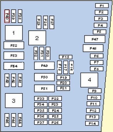
Type 2
Protected components
F1 | 30A/ 40A | Onboard supply control unit |
F2 | 20A | ABS control unit |
F3 | – | – |
F4 | 5A | Battery monitor control unit (with start/stop) Onboard supply control unit |
F5 | 15A | Horn and dual tone horn Dual tone horn relay |
F6 | – | not assigned |
F7 | 15A | Fuel pressure regulating valve |
F8 | – | not assigned |
F9 | 10A | Charge pressure control solenoid valve Activated charcoal filter solenoid valve 1 Turbocharger air recirculation valve |
F10 | 10A | 2009-2013: Air mass meter |
F11 | 10A | Lambda probe heater |
F12 | 10A | Lambda probe 1 heater after catalytic converter Lambda probe 2 heater after catalytic converter |
F13 | 15A | Mechatronic unit for dual clutch gearbox |
F14 | – | – |
F15 | 10A | Coolant circulation pump Continued coolant circulation pump |
F16 | – | – |
F17 | 5A | Control unit in dash panel insert (without start/stop) Steering column electronics control unit |
F18 | 30A | Amplifier |
F19 | 15A/ 25A | Voltage stabiliser (with start/stop) Display unit for front information display and operating unit control unit with control unit 1 for information electronics (without start/stop) Radio (2009-2014) |
F20 | 5A | Telephone control unit (2009-2014) Emergency call module control unit and communication unit (without start/stop) (2014-2017) |
F21 | – | – |
F22 | – | – |
F23 | 10A | Engine control unit Main relay |
F24 | 5A | Data bus diagnostic interface |
F25 | – | – |
F26 | – | – |
F27 | 5A | Exhaust flap 1 valve |
F28 | 15A | Engine control unit |
F29 | 5A | Auxiliary engine coolant pump relay |
F30 | – | – |
F31 | 30A | Wiper motor control unit Windscreen wiper motor |
F32 | – | – |
F33 | – | – |
F34 | – | – |
F35 | – | – |
F36 | – | – |
F37 | – | – |
F38 | 10A | Oil pressure switch for reduced oil pressure Oil level and oil temperature sender – Radiator fan control unit Low heat output relay High heat output relay Engine component current supply relay Charge pressure control solenoid valve Activated charcoal filter solenoid valve 1 Camshaft control valve 1 Turbocharger air recirculation valve Intake manifold flap valve Oil pressure control valve Piston cooling jet control valve Radiator fan Radiator fan 2 Charge air cooling pump Auxiliary pump for heating |
F39 | 5A | Clutch position sender (with start/stop) Brake light switch |
F40 | 20A | Ignition coil 1~4 with output stage |
F41 | – | – |
F42 | 5A | Engine component current supply relay |
F43 | – | – |
F44 | – | – |
F45 | – | – |
F46 | – | – |
F47 | 30A | Onboard supply control unit |
F48 | 30A/ 40A | ABS control unit |
F49 | 40A | Terminal 15 voltage supply relay 2 |
F50 | – | – |
F51 | – | – |
F52 | 40A/50A | 2009-2013: X-contact relief relay 2014-2017: X-contact relief relay Fuses on fuse holder C (instrument panel): ~40, 41, 42 |
F53 | 50A | 2009-2013: Fuse #32 on fuse holder C (instrument panel) 2014-2017: Fuses on fuse holder C (instrument panel): #32, 33, 34, 35, 36, 37 Driver seat adjustment thermal fuse 1 |
F54 | – | – |
SA1 | 150A/ 200A | Alternator |
SA2 | 80A | Power steering control unit Electromechanical power steering motor |
SA3 | 50A | Radiator fan control unit Radiator fan |
SA4 | – | – |
SA5 | 80A | Terminal 30 connection, fuse holder C |
SA6 | – | – |
SA7 | – | – |
Where is the daytime running light fuse? And f number?