The 1st generation Toyota Vitz was produced in 1998, 1999, 2000, 2001, 2002, 2003, 2004 and 2005 with the p10 – p12 marking. During this time, the model was updated several times. Toyota Platz presents a sedan made on a common base with Vitz. In our material you can find information describing the locations of electronic control units, the purpose of fuses and relays Toyota Vitz 1 with box diagrams and their photos with examples of execution. Note the cigarette lighter fuse.

The locations of the units and their design may differ from those shown and depend on the year of manufacture and the level of electrical equipment.
Contents
Boxes arrangement
General layout of electronic control units


Assignment
- oil pump relay (“START / STOP” system)
- fuse blox (models with “START / STOP” system)
- relay box No. 2 in the engine compartment
- fuse box
- ABS relay box
- starter control relay (“START / STOP” system)
- ABS modulatorright
- front airbag sensor
- mounting box in the engine compartment
- front left airbag sensor
- “START / STOP” control unit
- central lock control relay
- remote control receiver for central locking
- stability control unit
- electric power steering control unit (2SZ-FE)
- fuse box
- mounting box under the dashboard
- fog lamp relay (RS)
- SRS control unit
- electronic engine control unit
- automatic transmission selector lock control unit
- deceleration sensor (ABS, 4WD)
- fuel pump control relay
- transformer (“START / STOP” system)
- storage battery (“START / STOP” system).
Passenger compartment
Fuse and relay box
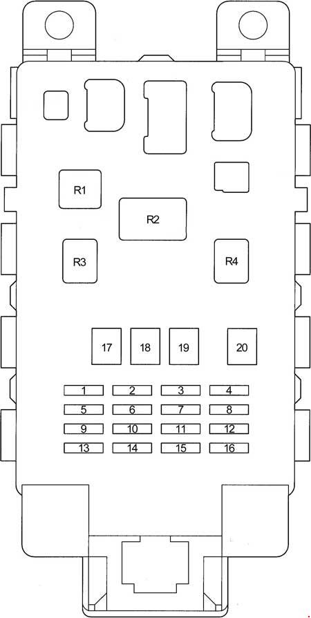
It is located under the panel, behind the protective cover, in the general diagram it is indicated at number 17.
RHD

LHD

Photo – an example of execution

Check your diagram on the box cover

Diagram

Protected components
| 1 | 10A GAUGE – Instruments, ABS, air conditioning, reversing lamps, charging system, instrument cluster, dual lock, door lock control unit, engine control unit, gearbox control unit, daytime running lights, warning buzzer, sunroof, power windows, transmission selector lock gear, direction indicators, alarm, heater |
| 2 | 10А DEF RLY – Heated rear window, heated mirrors |
| 20А DEF – Heated rear window, heated mirrors | |
| 3 | 25A D / L – Double lock, door lock control unit |
| 4 | 7.5A TAIL – Front fog light, headlights, headlight range control, warning buzzer, rear fog light, side light |
| 5 | – |
| 6 | 20A WIPER – Front wiper and washer, rear wiper and washer, door lock |
| 7 | 7.5А ECU − B – Headlights, rear fog light |
| 8 | 15A FOG – Front fog light |
| 9 | 15A ACC – Cigarette lighter, clock, instrument cluster, warning buzzer, multi-information display, socket, audio system, power mirrors |
| 10 | 7.5A ECU-IG – ABS, interior lighting, multi-information display, auxiliary heater (PTC), cooling fan, SRS airbag system, heater |
| 11 | 7.5А OBD – Diagnostic connector |
| 12 | 10А HAZ – Direction indicators, alarm |
| 13 | 7,5A A.C – Air conditioning, heater |
| 14 | 10A S-HTR – Heated seats |
| 15 | – |
| 16 | 10A STOP – Engine control unit, gearbox control unit, gearbox selector lock, brake light |
| 17 | 50А AM1 – Fuses: “ACC”, “GAUGE”, “DEF” (“DEF RLY”,), “S-HTR”, “WIPER”, “ECU − IG” |
| 18 | 30A POWER – Windows, sunroof |
| 19 | 40А HTR – Air conditioning, heater |
| 20 | 30A DEF – Heated rear window, heated mirrors |
| Relay | |
| R1 | Heater |
| R2 | Hazard warning lights (turn signals) |
| R3 | Power relay (windows, sunroof) |
| R4 | Fuel Pump (Circuit Opening (C / OPN)) |
The fuse number 9, 15A, is responsible for the operation of the cigarette lighter, another fuse is located in the block under the hood.
Engine compartment
Fuse and relay box
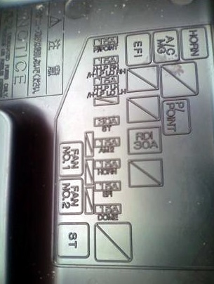
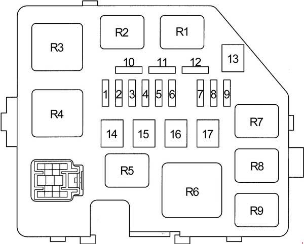
This unit is located on the left side of the engine compartment, next to the battery.
Photo

Check your diagram on the box cover

Diagram

Designation
| 1 | 15A DOME – Clock, instrument cluster, dual lock, headlights, interior lighting, warning buzzer, multi-information display, audio system, door lock control unit |
| 2 | 15A EFI – Engine control unit, immobilizer, transmission control unit |
| 3 | 15A HORN – Sound signal |
| 4 | 15A AM2 – Charging system, instrument cluster, engine control unit, immobilizer, gearbox control unit, multi-information display, SRS airbag system, ignition system |
| 5 | 30A ST – Starting system |
| 6 | – |
| 7 | 10A H − LP LH – Left headlight, headlight range control |
| 8 | 10A H − LP RH – Left headlight, headlight range control |
| 9 | 15A P / POINT – Socket |
| 10 | Spare fuse |
| 11 | Spare fuse |
| 12 | Spare fuse |
| 13 | – |
| 14 | – |
| 15 | 30A RDI – Cooling fan |
| 16 | 50A HTR SUB1 – Auxiliary heater (PTC) |
| 17 | – |
| Relay | |
| R1 | Cooling fan |
| R2 | Cooling fan |
| R3 | Starter |
| R4 | – |
| R5 | Power socket |
| R6 | Auxiliary heater (PTC) |
| R7 | EFI |
| R8 | A / C Compressor Clutch |
| R9 | Sound signal |
Additional box
Diagram

Appointment
| 1 | 10А H-LP HI RH – Headlights (daytime running lights) |
| 2 | 10А H-LP HI LH – Instrument cluster, headlights (daytime running lights) |
| Relay | |
| R1 | Headlights |
| R2 | Dimmer (DIM) |
| R3 | – |
ABS box
Diagram

Assignment
- 1 – ABS fuse # 3 (models without VSC); no (models with VSC)
- A – no (models without VSC); ABS MTR relay (models with VSC)
- B – ABS MTR relay (models without VSC); ABS CUT relay (models with VSC)
- C – ABS SOL relay (models without VSC); no (models with VSC).
Power fuse box
It is located on the positive terminal of the storage battery and is made in the form of high-power fuse-links.
Diagram

Designation
- 60А MAIN – Fuses: “EFI”, “DOME”, “HORN”, “ST”, “AM2”, “H − LP LH”, “H − LP RH”, “H − LP LH (HI)”, ” H − LP RH (HI) ”,“ H − LP LH (LO) ”,“ H − LP RH (LO) ”
- 80A – “START / STOP” system
- ALT 100 / 120A – Fuses: “ECU-B”, “TAIL”, “D / L”, “OBD”, “RDI”, “AM1”, “HAZ”, “HTR”, “HTR-SUB1″, ” POWER ”,“ STOP ”,“ DEF ”, Charging system
- 60A ABS – ABS
If you have any questions, ask in the comments. Together we will try to answer them.
 FuseAndRelay.com
Hi There,
wonderful post, the fuel pump control relay shown as item 23 in your diagram, is difficult to realize it’s position, is it on the center console, or is it on the inside of the right chassis rail, shown from a left side quartering tail shot it’s tough to figure out a no start condition and in trying to isolate the fuel pump fuses/relays which is imperative.
Thanks
Don
Barbados
2001 TOYOTA VITZ RS 15OO CC
I have toyota vtiz 2013 modle its door remote is not working
Hi,
What is the function of a circuit board under the driver seat of toyota vitz 2000 right hand drive Japanese model.
Alternator not charging the battery../old shape vitz
I would like get the location of oil control valve fuse on vitz 2002 model pls
Hello there.
There is an issue with the gear shift of toyota platz 2001 while the car is on acceleration it happen to have long fuel racing and later the gear will engage and later there will be like gear jump to the next one
Hi there, I have a a Toyota Vitz engine 1SZ , frame 1SCP-10, when I depress the over drive switch nothing is responding, the light doesn’t show on the dashboard and the transmission is not responding, can it be a fuse problem? Please advise, thanks
I have a Toyota vitz 2008 but it’s dashboard light doesn’t show also key nob isn’t turning
Hi I have a vitz 2012 model whenever I open the door the clock on the dashboard doesn’t pop. Only when the vehicle started then it pops up with the mileage etc.
Could any please help me identify what is the problem and solution to resolve same?