The 1st generation Toyota Caldina T19x was produced in 1992, 1993, 1994, 1995, 1996, 1997 as a station wagon. The most popular were the models marked T 195 / 196 with five doors. In this article we will show a description of fuses and relays Toyota Kaldina T 195/196 with box diagrams and their locations. Highlight the cigarette lighter fuse.

The design of the boxes and the purpose of the elements in them may differ from the one presented and depend on the year of manufacture and the level of equipment of your car. Check the purpose of the elements with your diagrams on the box cover.
Passenger compartment
In the passenger compartment, the fuse box is located under the dashboard on the driver’s side behind a protective cover.

Example of a diagram from the box cover

Diagram

Assignment
| 1 | 5А DEFOG / IDLE-UP – System for increasing idle speed, electronic engine control unit |
| 2 | 30А DEFOG – Heated rear window |
| 3 | 15A ECU – IG – Anti-lock braking system, shift lock system |
| 4 | 10A TAIL – Front and rear dimensions, license plate light |
| 5 | 5A STARTER – Starter, engine control unit |
| 6 | 5A IGNITION – Ignition, ECM |
| 7 | 10A TURN – Direction indicators |
| 8 | 20А WIPER – Wipers and washers |
| 9 | 15A METER – Instrument cluster |
| 10 | 7,5А PANEL – Illumination of a combination of devices and switches |
| 11 | 15А LIGHTER / RADIO – Electric side mirrors, cigarette lighter, clock, radio tape recorder |
| 12 | 15A FOG – Front fog lights |
| 13 | 30А DOOR – Central locking |
| 14 | 15А STOP – Stop lights |
The fuse responsible for the cigarette lighter is located at number 11 at 15A.
Some relays can be attached to the back of the box.
- Main power relay
- Relay dimensions
- Heated rear window relay
Separately, closer to the left drain, some additional fuses can be attached.
Diagram

Appointment
- 15A FR DEF – Heated wiper blades
- 15A ACC SOCKET – Additional sockets
And in the panel on the left side: 1 20A F / HTR – Fuel heating.

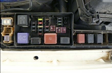
Engine compartment
The main fuse and relay box is located on the left side of the engine compartment, next to the battery. Several variants of its execution are possible.
Type A
Photo – example

Diagram

Protected components
| Fuses | |
| а | 50A HTR (heater) |
| b | 40A MAIN (main fuse-link) |
| с | 30A CDS (condenser fan) |
| d | 30A RDI (air conditioner radiator fan) |
| e | 100A ALT (charging) |
| f | 50A ABS (ABS) |
| 1 | 15A HEAD RH * (right headlight) |
| 2 | 15A HEAD LH * (left headlight) |
| 3 | 15A EFI (injection system) |
| 4 | spare |
| 5 | spare |
| 6 | 15A HAZARD |
| 7 | 10A HORN (beep 🙂 |
| 8 | – |
| 9 | 7.5A ALT SENCING (charging) |
| 10 | 20A DOME (electric drive and interior lighting) |
| 11 | 30A AM2 (AM3 circuit of the ignition switch, conclusions IG2 ST2) |
| Relay | |
| А | STARTER – Starter |
| В | HEATER – Heater |
| С | EFI MAIN – Injection system |
| D | ENGINE MAIN – Main relay |
| Е | HEAD – Headlights |
| F | HORN – Signal |
| G | FAN # 1 – Radiator fan |
Type B
Photo – example
Diagram

Protected components
| Relay A – relay No. 1 e / dv. cooling fan, B – starter relay, C – horn relay, D – headlight relay, E – injection system relay, F – relay No. 2 e / dv. cooling system fan, G – relay No. 3 e / dv. cooling fan, H – air conditioner relay; |
| Fusible links 1 – ALT 100A (120A for 3S-FSE engines), 2 – ABS 60A, 3 – HTR 40A; |
| Fuses 4 – DOME 7,5A, Interior lighting |
Separate fuses and relays can be installed outside of this unit.