Toyota Probox five door station wagon was produced in 2002, 2003, 2004, 2005, 2006, 2007, 2008, 2009, 2010, 2011, 2012, 2013, 2014 and up to the present. During this time, the model received an update. Also known as Toyota Succeed. In this article, we will show a description of the fuses and relays of Toyota Probox Succeed with box diagrams and locations from the location.

The purpose of the elements in the boxes may differ from the one presented. Check the assignment with your diagrams on the box cover.
Passenger compartment
In the passenger compartment, the main fuse and relay box is located at the bottom of the dashboard behind a protective cover.

Photo example of execution

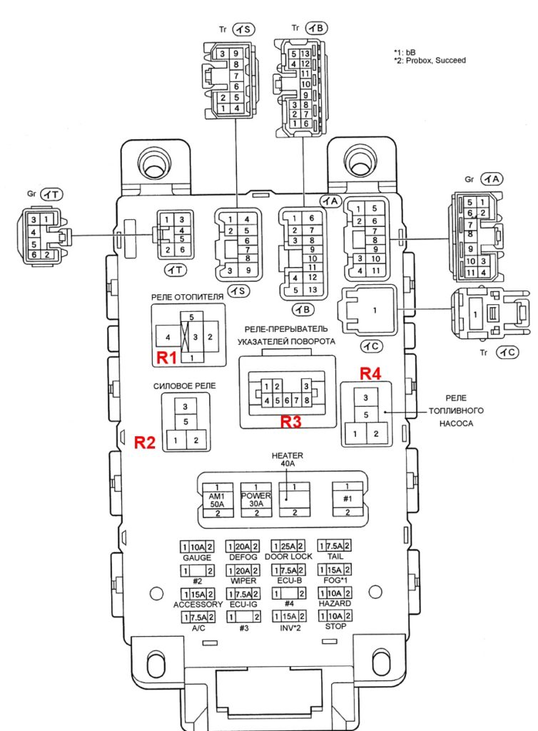
Diagram from the box cover

Diagram
Assignment
R1- Heater relay
R2 – Main power relay
R3 – Turn signal interrupter relay
R4 – Fuel pump relay
AM1 (50A) – Power thick wire goes directly from the battery to the ignition switch and ACC
Power (30A) – Power windows, sunroof
Heather (40A) – Air conditioner with manual, automatic control
Gauge (10A)
Charging system (models up to 08.2002).
Engine management system.
Automatic transmission electronic control system.
Anti-lock braking system.
Automatic transmission indicators.
Power windows.
Central locking.
A warning system about a key left in the ignition lock and a non-switched off lighting.
Seat belt warning system.
Electric sunroof.
A combination of devices.
Watch.
Direction indicators and emergency gang.
Reversing lights.
Air conditioner with manual, automatic control.
Airbags (models from 08.2002).
Anti-lock braking system, traction control system and stability control system (models from 08.2003).
Def (20A) – Heated rear window.
Door (25A) – Central locking.
Tail (7.5A)
A warning system about a key left in the ignition lock and a non-switched off lighting.
A combination of devices.
Watch.
Headlights (halogen).
Dimensions and lighting.
Rear fog lamps.
Fog lights (up to 08.2002).
Manual air conditioner (until 08.2002).
Headlights (xenon).
Wiper (20A) – Windshield and rear window wiper and washer.
Electronic B (7.5A)
Engine management system.
Automatic transmission electronic control system.
Rear fog lamps.
Manual air conditioner (until 08.2002).
Immobilizer system (from 08.2002).
Anti-lock braking system, traction control system and stability control system (models from 08.2003).
Rear view system (2WD models from 08.2003).
Fog (15A) – Fog lights.
Accessory (15A)
Electric drive of mirrors.
Audio system.
Cigarette lighter.
Connector for connecting additional. equipment.
Rear view system (2WD models from 08.2003).
Electronic Ig (7.5A)
Fan electric drive (up to 08.2002).
Anti-lock braking system.
Interior lighting lamps.
Air conditioner with manual and automatic control.
Fan electric drive (from 08.2002).
Heated rear window (from 08.2002).
Anti-lock braking system, traction control system and stability control system (models from 08.2003).
Rear view system (2WD models from 08.2003).
Haz (10A) – Direction indicators and hazard warning lights.
A / C (7.5A) – Manual and automatic air conditioner.
Invertor (15A) – Connector for connecting additional equipment.
Stop (10A) – Stop lights, Engine management system, Anti-lock braking system
The fuse number designated as Accessory 15A is responsible for the cigarette lighter.
Engine compartment
Under the hood, the main fuse and relay box is located on the left side of the engine compartment, next to the battery.
Example of a diagram from the cover

Photo

Diagram
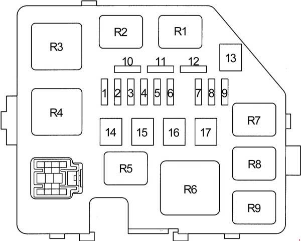
Designation
| 1 | 15A DOME – Clock, instrument cluster, dual lock, headlights, interior lighting, warning buzzer, multi-information display, audio system, door lock control unit |
| 2 | 15A EFI – Engine control unit, immobilizer, transmission control unit |
| 3 | 15A HORN – Sound signal |
| 4 | 15A AM2 – Charging system, instrument cluster, engine control unit, immobilizer, gearbox control unit, multi-information display, SRS airbag system, ignition system |
| 5 | 30A ST – Starting system |
| 6 | – |
| 7 | 10A H − LP LH – Left headlight, headlight range control |
| 8 | 10A H − LP RH – Left headlight, headlight range control |
| 9 | 15A P / POINT – Socket |
| 10 | Spare fuse |
| 11 | Spare fuse |
| 12 | Spare fuse |
| 13 | – |
| 14 | – |
| 15 | 30A RDI – Cooling fan |
| 16 | 50A HTR SUB1 – Auxiliary heater (PTC) |
| 17 | – |
| Relay | |
| R1 | Cooling fan |
| R2 | Cooling fan |
| R3 | Starter |
| R4 | – |
| R5 | Power socket |
| R6 | Auxiliary heater (PTC) |
| R7 | EFI |
| R8 | A / C Compressor Clutch |
| R9 | Sound signal |
Individual elements can be installed outside this box. For example, a high-power fuse box can be attached to the positive terminal of the battery.
Very good feature.
Mucha importancia me salvó las fallas
Good
I found this very Helpful…and I saved Costs alot…
I love is how you are helping me to get all this