The 1st generation Toyota RAV4 was produced in 1994, 1995, 1996, 1997, 1998, 1999, 2000 and was designated as CA10W / XA10W. During this time, the model has been restyled. In this article you will find the locations of the electronic control units, a description of the fuses and relays of the Toyota Rav 4 1st generation with box diagrams and photographs. Highlight the cigarette lighter fuse.

The number of elements in boxes may differ from that shown and depends on the year of manufacture, the region of delivery and the level of electrical equipment.
Contents
Passenger compartment
Location
General layout diagram

Description
- Fuse box
- Relay box
- ABS ECU
- Fuse box No. 2
- Air conditioner amplifier
- Door lock control relay
- Cruise control ECU
- Fuse and relay box
- Airbag sensor unit
- ECU for gearshift lock
- Engine control module

R1 – Rear wiper relay
Fuse box
In the general layout diagram, it is indicated under the number 1.

Diagram
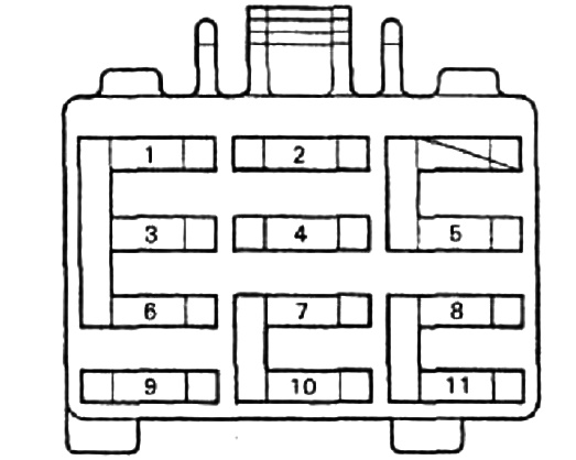
Assignment
| 1 | 7,5A Direction indicators “TURN” |
| 2 | 7,5A Heated rear window “DEF-I / UP” |
| 3 | 10A Instruments “GAUGE” |
| 4 | 7,5A Ignition “IGN” |
| 5 | 7,5A Stop light “STOP” |
| 6 | 10A Heated seats “SEAT-HTR” |
| 7 | 7,5A Electronic control unit “ECU-IG” |
| 8 | 7,5A Dimensions “TAIL” |
| 9 | 15A Cigarette lighter and radio “CIG & RAD” |
| 10 | 20A Screen wiper “WIPER” |
| 11 | 10A Panel “PANEL” |
The fuse number 9 is responsible for the cigarette lighter.
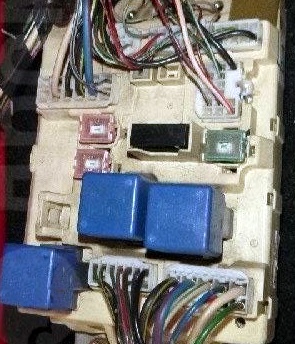
Relay box
In the general layout diagram, it is indicated under the number 2.
Diagram

Appointment
- R1 – Open circuit relay
- R2 –
- R3 – Rear fog lamp relay (European models)
- R4 – Direction indicator
Fuse box No. 2
In the general layout diagram, it is indicated under the number 4.
Type A
Diagram

Decoding
Circuit breakers
- 30A Power – Electric windows, electric door lock system
- 30A DEF – Heated rear window
- 40А AM1 – Fuses “CIG & RAD”, “WIPER”, “GAUGE”, “ECU-IG”, “TURN”, “TAIL” and “PANEL”
- Interference filter
Relay
| R1 | Heater |
| R2 | Main power relay |
| R3 | Back light |
| R4 | Integration relay |
Type B
Diagram
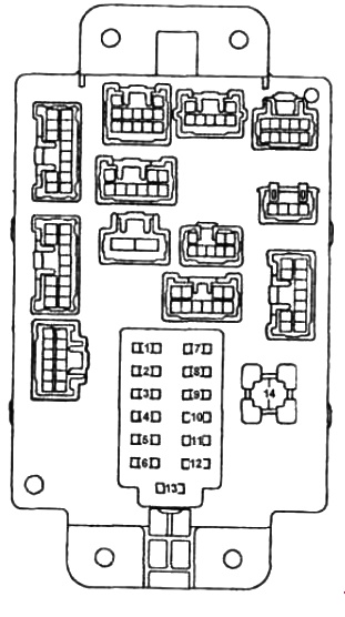
Designation
| 1 | 15A “PWR OUTLET” power take-off for connecting external devices |
| 2 | 15A “CIG” cigarette lighter, audio system, electric adjustment of external mirrors |
| 3 | 10A “SRS-ACC” SRS system |
| 4 | 20A “WIPER” wipers and washers, headlight washers |
| 5 | 10A “ECU-IG” automatic transmission control unit, injection system |
| 6 | 10A “TURN & GAUGE” instruments and indicators, direction indicators, daytime lighting system |
| 7 | 10A “STOP” brake lights |
| 8 | 15A “TAIL” dimensions, reversing lights, headlight range control |
| 9 | 10A “MIR-HTR” outside mirror heaters |
| 10 | 10A “SRS-B” SRS indicator |
| 11 | 10A “HORN” horn |
| 12 | 20A “DEFOG” tailgate glass heater |
| 13 | 10A “AM 1” (for PWR OUTLET, SRS-ACC, CIG, WIPER, ECU-IG, TURN & GAUGE fuses) |
| 14 | 30A “FWR” central locking, electric sunroof, electric glass lifters |
Fuse and relay box
In the general layout diagram, it is indicated under the number 8.
Diagram

Decoding
1 – Air conditioning system
R1 – Heater relay
Engine compartment
Location
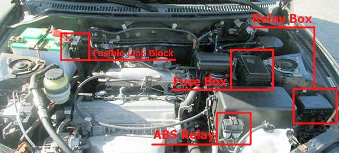
General layout diagram

Appointment
- Fuse and relay box
- Relay box
- ABS relay
- Fusible block
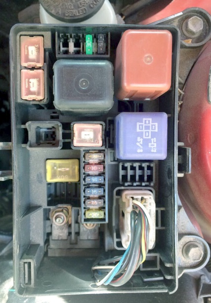
Fuse and relay box
Installed on the left side of the engine compartment, next to the pillar.
Execution example
Diagram

Assignment
| 1 | 10A * Left headlamp – low beam “HEAD LH-L” |
| 2 | 10A * Right headlamp – low beam “HEAD RH-L” |
| 3 | 10A * LH headlamp – high beam “HEAD LH-H |
| 3 | 15A ** Left headlight – “HEAD LH” |
| 4 | 10A * Right headlight – high beam “HEAD RH-H” |
| 4 | 15A ** Right headlight – “HEAD RH” |
| 5 | 5A Generator “ALT-S” |
| 6 | 10A Salon “DOME” |
| 7 | 15A Alarm “HAZ-HORN” |
| 8 | 15A Injection system “EFI” |
| 9 | 15A Radio “RAD” |
| 10 | 20A “AM2” – charging system |
| 11 | 30A “CDS FAN” Electric cooling fan |
| 12 | 30A “RDI FAN” Electric cooling fan |
| 13 | 40A “H-LP CLN” (LHD) – Headlight cleaner |
| 13 | 40A “HTR” (right-hand drive) – heater fan |
| 14 | 30A “MAIN No. 1” – starting system, headlight fuses |
| 15 | 60A “ABS” – ABS |
| 16 | 100A Alternator “ALT” (RHD) |
| Relay | |
| A | Main motor relay |
| B | Headlight control relay |
| C | Starter relay |
Relay box
Diagram

Designation
| A | Main relay of the injection system |
| B | Headlamp switching relay |
| C | A / C compressor electromagnetic clutch relay |
| D | Relay for electric fan No. 1 |
| E | Relay for electric fan No. 3 |
| F | Relay for electric fan No. 2 |
| G | Horn relay |
Fusible block
Installed next to the battery.

Protected components
- 80A MAIN – Fuses “AM 2”, “HAZ-HORN”, “EFI”, “DOME”, “RADIO” and “ALT-S”
- 100A ALT – Rear lights, fuses “ABS”, “RADIO”, “HTR”, “AM 1”, “POWER”, “STOP” and “DEF”
- 50A HTR – air conditioner and heater (A / C fuse)
That’s all. If you know how to make this article better, write in the comments.
Very helpfull
Hi! The photo you uploaded doesnt follow the manual specifications regarding fuses Amperage. Does it work properly anyways?
Salut problème des capteurs des roues Lexus RX 350