The 1st generation Toyota Highlander was produced in 2000, 2001, 2002, 2003, 2004, 2005, 2006 and 2007 with the U20 designation. In some countries it is known as Toyota Kluger V. In this publication we will show the locations of the electronic control units, describe in detail the fuses and relays of the Toyota Highlander 1 Kluger with box diagrams and photo examples of their execution. Note the cigarette lighter fuse.

The arrangement of blocks and elements in them may differ from that shown and depends on the year of manufacture, the level of equipment and the region of delivery. Check the information with your diagrams on the box cover.
Contents
Passenger compartment
Location
Layout
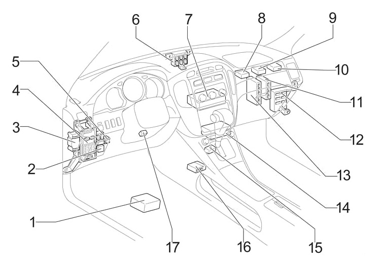
Assignment
- Navigation control unit
- Heater relay
- Relay box
- Fuse box
- Turn signal relay (alarm)
- Distribution block
- Air conditioning control unit (without navigation)
- Anti-theft control unit
- Network gateway block
- Key transponder computer
- Body electrical control unit
- Distribution block
- The engine control unit
- Air conditioning control unit (with navigation)
- Gear selector lock block
- Central airbag unit
- Key transponder amplifier
Fuse box
It is located at the bottom of the dashboard.

Diagram
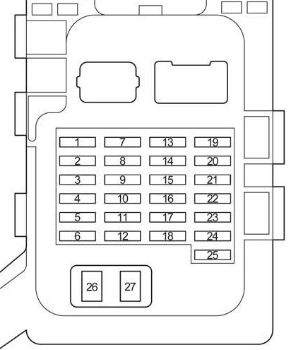
Circuits protected
| 1 | 7.5A IGN – 2001-2003: Instrument Cluster, SRS Airbag System |
| 10A IGN – 2004-2007: Instrument Cluster, SRS Airbag System, Multiport Fuel Injection System / Sequential Multiport Fuel Injection System, Front Passenger Classification System | |
| 2 | 7,5A RADIO NO.2 – Audio system, gear selector lock, navigation, rear passenger entertainment system, air conditioning, body ECU |
| 3 | 15A CIG – Cigarette lighter |
| 4 | 20A D RR DOOR – 2001-2003: Window Regulator |
| 20A D RR DOOR – 2004-2007: Window Regulator | |
| 5 | 15A PWR OUTLET – 2001-2003: Sockets |
| 15A PWR OUTLET – 2004-2007: Sockets | |
| 6 | 10A FR FOG – 2001-2003: Front fog light |
| 20A FR FOG – 2004-2007: Front fog light | |
| 7 | 15A SRS-IG – 2001-2003: SRS Airbag System |
| 8 | 15A ECU-IG – 2001-2003: Sunroof, ABS, VSC, gear selector lock, charging system, cruise control, hazard warning lights, starting system |
| 10A ECU-IG – 2004-2007: Sunroof, ABS, VSC, gear selector lock, charging system, starting system | |
| 9 | 25A WIPER – Wiper and washer |
| 10 | 20A P RR DOOR – 2001-2003: Window Regulator |
| 20A P RR DOOR – 2004-2007: Window Regulator | |
| 11 | 25A P FR DOOR – 2001-2003: Window Regulator, Door Lights, Central Locking |
| 25A D FR DOOR – 2004-2007: Window Regulator, Door Lights, Central Locking | |
| 12 | 20A S / ROOF – Hatch |
| 13 | 15A HEATER – 2001-2003: Air Conditioner, Cooling Fan, Heated Rear Window, Heated Mirrors, Instrument Cluster |
| 10A HEATER – 2004-2007: Air Conditioner, Cooling Fan, Heated Rear Window, Heated Mirrors, Instrument Cluster | |
| 14 | 7.5A IG1 – Reversing lamps, VSC, multiport fuel injection system / sequential multiport fuel injection system, heated mirrors, central locking, navigation, body ECM |
| 15 | 15A RR WIP – Rear wiper |
| 16 | 20A STOP – Stop lamps, auxiliary brake light, ABS, VSC, gear selector lock, cruise control, multiport fuel injection system / sequential multiport fuel injection system, trailer lighting, body ECM |
| 17 | 7,5A OBD – Diagnostic connector |
| 18 | 15A SEAT HTR – Heated seats |
| 19 | 15A IG2 – Multiport fuel injection system / sequential multiport fuel injection system, charging system, starting system |
| 20 | 20A WASHER – Washer, low level indicator of washer fluid |
| 21 | 7,5A RR FOG – Rear fog light |
| 22 | 20A FR DEF – Air conditioning, heated mirrors |
| 23 | 20A D FR DOOR – 2001-2003: Window Regulator, Door Lights |
| 20A D FR DOOR – 2004-2007: Window Regulator, Door Lights, Bodywork ECM | |
| 24 | 10A TAIL – Side light, license plate light, instrument panel light |
| 25 | 7,5A PANEL – Illumination of the instrument panel, lighting of the trailer |
| 26 | 40A AM1 – Multiport fuel injection system / sequential multiport fuel injection system |
| 27 | 30A POWER – Power Seats |
The fuse number 3 at 15A is responsible for the operation of the cigarette lighter.
Some relays can be attached to the back of the unit.
Scheme

Appointment
- R1 Side light
- R2 Fog light
- R3 Auxiliary relay (ACC)
Relay box
Diagram

Designation
- R1 Fuel Pump (Circuit Opening)
- R2 Heated seats
- R3 Heated brush rest zone
Additional elements
Diagram

Designation
- Sunroof control unit
- Distribution block
- Rear passenger entertainment control unit (without rear heater)
- Central locking control unit
- Rear heater relay
- Audio amplifier
- Rear seat entertainment control unit
- Glass lifters control unit
Engine compartment
Location
Layout

Decoding
- Fuse and relay box
- Brake control unit
- ABS relay box
- Additional fuse box
Fuse and relay box
It is located under the hood on the left side.
Photo example

Diagram
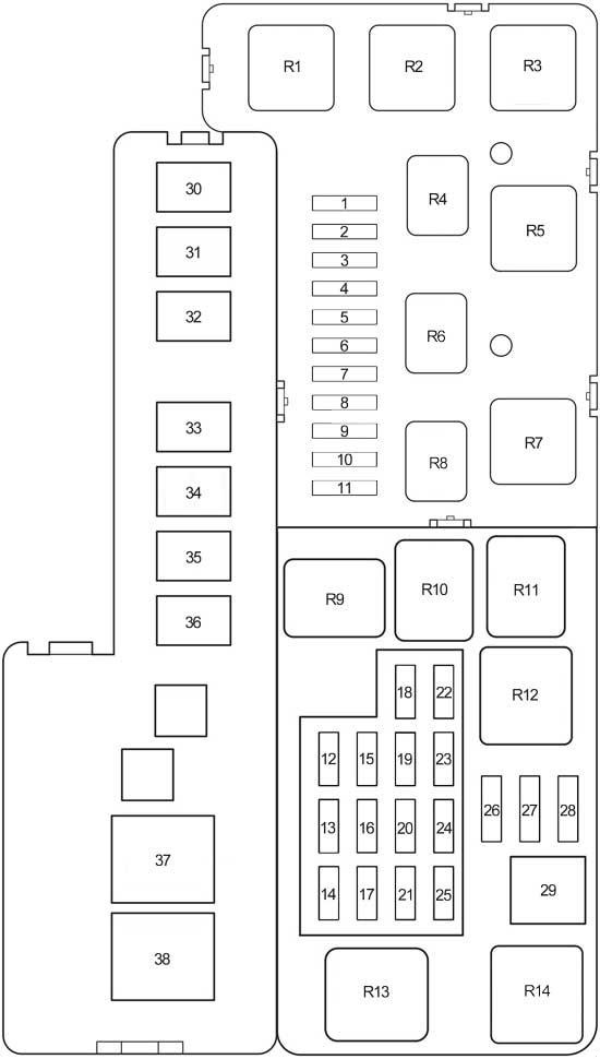
Assignment
| 1 | – |
| 2 | – |
| 3 | 25A A / F – 2004-2007: Air Fuel Ratio Sensor |
| 4 | 7.5A CRT – 2004-2007: Rear Seat Entertainment, Navigation |
| 5 | 7,5A STARTER – 2004-2007: Multiport fuel injection system / sequential multiport fuel injection system |
| 6 | 7,5A STARTER – 2001-2003: Multiport fuel injection system / sequential multiport fuel injection system |
| 7 | 7.5A ABS3 – 2001-2003: VSC |
| 10A EFI NO.2 – 2004-2007: Multiport fuel injection system / sequential multiport fuel injection system | |
| 8 | 15A HEAD LP RH LWR – 2001-2003: Low beam right |
| 10A ETCS – 2004-2007: Multiport fuel injection system / sequential multiport fuel injection system | |
| 9 | 15A HEAD LP LH LWR – 2001-2003: Low beam left |
| 15A RR HTR – 2004-2007: Rear A / C (Heater) | |
| 10 | 25A A / F – 2001-2003: Air Fuel Ratio Sensor |
| 15A H − LP RH LWR – 2004-2007: Low beam right | |
| 11 | 15A H − LP LH LWR – 2004-2007: Low beam left |
| 12 | 7,5A ALT − S – Charging system |
| 13 | 20A POWER OUTLET2 – 2004-2007: Sockets |
| 14 | 20A TOWING – Trailer lighting |
| 15 | 10A HORN – Sound signal |
| 16 | 15A SECURITY – Anti-theft system |
| 17 | 10A HEAD LP RH UPR – 2001-2003: High Beam Right |
| 10A H − LP RH UPR – 2004-2007: High Beam Right | |
| 18 | 7,5A ECU-B – Anti-theft system, air conditioning, VSC, instrument cluster, central locking, sunroof, front passenger classification system, body electrical control unit |
| 19 | 20A EFI – 2001-2003: Multiport fuel injection system / sequential multiport fuel injection system, fuel pump, immobilizer |
| 20A EFI NO.1 – 2004-2007: Multiport fuel injection system / sequential multiport fuel injection system, fuel pump | |
| 20 | 25A DOOR LOCK – Central locking, anti-theft system |
| 21 | 10A HEAD LP LH UPR – 2001-2003: High Beam Left |
| 10A H − LP LH UPR – 2004-2007: High Beam Left | |
| 22 | 25A RADIO NO.1 – Audio system |
| 23 | 10A DOME – Interior Lighting, Personal Lighting, Ignition Switch Lights, Central Locking, Instrument Cluster, Navigation, Sun Visor Mirror Lights |
| 24 | Short |
| 25 | 15A HAZARD – Hazard alarm, instrument panel illumination, trailer illumination |
| 26 | 7.5A Spare fuse |
| 27 | 15A Spare fuse |
| 28 | 25A Spare fuse |
| 29 | 40A MAIN – 2001-2003: Fuses: “HEAD LP RH LWR”, “HEAD LP LH LWR”, “HEAD LP RH UPR”, “HEAD LP LH UPR” |
| 40A MAIN – 2004-2007: Fuses: “H − LP RH LWR”, “H − LP LH LWR”, “H − LP RH UPR”, “H − LP LH UPR” | |
| 30 | 30A AM2 – Multiport fuel injection system / sequential multiport fuel injection system, starting system |
| 31 | 40A ABS2 – 2001-2003: ABS, VSC |
| 50A ABS2 – 2004-2007: ABS, VSC | |
| 32 | 40A ABS2 – 2001-2003: ABS, VSC |
| 30A ABS2 – 2004-2007: ABS, VSC | |
| 33 | 50A HEATER – 2001-2003: Air Conditioner |
| 50A HTR – 2004-2007: Air Conditioner | |
| 34 | 30A RDI – Cooling fan |
| 35 | 30A RR DEF – Heated rear window |
| 36 | 30A CDS – Cooling fan |
| 37 | 140A ALT – Fuses: “ABS1”, “ABS2”, “RDI”, CDS “,” RR DEF “,” HEATER “,” AM1 “,” AM2 “,” TAIL “, “PANEL”, “STOP”, “S / ROOF”, “SEAT HTR” |
| 38 | 50A RDI |
| Relay | |
| R1 | Cooling fan (FAN NO.1) |
| R2 | Starter |
| R3 | Cooling fan (FAN NO.3) |
| R4 | Air Fuel Ratio (A / F) Sensor |
| R5 | Inverter |
| R6 | – |
| R7 | Cooling fan (FAN NO.2) |
| R8 | – |
| R9 | A / C Compressor Clutch (MG CLT) |
| R10 | Sound signal |
| R11 | Engine control unit (EFI) |
| R12 | Heated rear window |
| R13 | Headlights (HEAD LAMP) |
| R14 | – |
ABS relay box
Diagram

Designation
- 1 –
- R1 –
- R2 – ABS relay
- R3 – ABS relay
Additional box
Diagram from the box cover

Appointment
- DRL 7.5А – Daytime running lights
- R1 Daytime running lights relay (DRL NO.2)
- R2 Daytime running lights relay (DRL NO.4)
- R3 Daytime running lights relay (DRL NO.3)
There is something to add to the material – write in the comments.
Its good siet I like it
My fuse boxes look nothing like these fuse boxes. I have a 2008 right hand drive Toyota kluger. I had to put a new alternator in it plus a brand new battery. Now it won’t start. Power is going to everywhere accept power windows, and ignition. Although the lights on the ignition panel come on. I think the problem lies the the ABS and brake malfunction lights coming on.
Where is the fuse for the cruise control, for a 2007 Kluger Grande?
where is the R1 Fuel Pump (Circuit Opening) located?