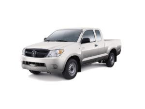
The 7th generation Toyota Hilux was produced in 2004, 2005, 2006, 2007, 2008, 2009, 2010, 2011, 2012, 2013, 2014 and 2015 with the designation AN10 / AN20 / AN30. During this time, the model has been restyled. In this article, you will find a description of the locations of the electronic control units, the purpose of fuses and relays of the 7th generation Toyota Hilux with photographs and box diagrams. Let’s highlight the fuse responsible for the cigarette lighter.

Depending on the region of delivery and the year of manufacture, a different design of boxes and an arrangement of elements is possible. Check the information with your diagrams on the box cover.
Contents
Passenger compartment
Location
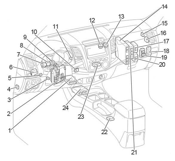
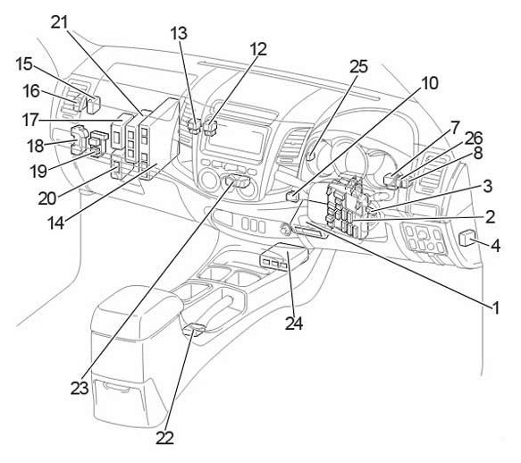
General layout of boxes in the cabin
LHD

RHD

Assignment
- Air conditioner amplifier / Viscous heater booster (without air conditioner)
- Fuse Box / Integrated Relay
- Key transponder amplifier
- Four-wheel drive control unit (rear differential lock)
- LHD: Side light relay (August 2006 – June 2011)
- LHD: Relay for daytime running lights
- Turn signal relay
- A / C clutch relay
- LHD: Side light relay (up to August 2006)
LHD: Rear fog light relay (from Aug 2006) - Distribution connector
- LHD: Side light relay (from June 2011)
- Auxiliary heater relay (PTC No.2)
- Auxiliary heater relay (PTC No.1)
- The engine control unit
- Central locking receiver
- Anti-theft control unit
- All-wheel drive control unit
- Relay box (from June 2011)
- Relay box (until June 2011)
- Turbo Motor Driver
- Transmission control unit
- Selector lever lock control unit
- Air conditioner control unit
- Airbag control unit
- RHD: Side light relay
- RHD: Rear fog light relay
Fuse box
It is located under the dashboard on the driver’s side behind a protective cover.

LHD

RHD

Example of a diagram from the box cover

Daigarm

Designation
| 1 | 15A INJ – Multiport fuel injection system / sequential multiport fuel injection system |
| 2 | 7,5A OBD – On-board diagnostics system |
| 3 | 10A STOP – Stop lights, auxiliary stop light, multiport fuel injection system / sequential multiport fuel injection system, ABS, TRC, VSC and shift lock control system |
| 4 | 10A TAIL – Instrument panel lighting, fog lights, headlight range control, front side lights, rear side lights, license plate lights, multiport fuel injection system / sequential multiport fuel injection system, multifunction display, daytime running light system and automatic control system headlights |
| 5 | 15A PWR OUT – Electrical outlet |
| 6 | 7,5A ST – Starting system, instruments and indicators, multiport fuel injection system / sequential multiport fuel injection system |
| 7 | 10A A / C – Air conditioning system |
| 8 | 7,5A MET – Instruments and indicators and DPF system |
| 9 | 15A CIG – Cigarette lighter |
| 10 | 7.5A ACC – Audio System, Electrical Outlet, Clock, Power Mirror System, Shift Lock Control System and Multifunction Display |
| 11 | 7,5A IGN – Multiport fuel injection system / sequential multiport fuel injection system, SRS airbags and fuel pump |
| 12 | 20A WIP – Windscreen wiper and washer |
| 13 | 10A ECU-IG & GAUGE – Air Conditioning System, Charging System, Rear Differential Locking System, ABS, TRC, VSC, Hazard Lights, Indicators, Reversing Lights, Multiport Fuel Injection System / Sequential Multiport Fuel Injection System, Lock Control System gearshifts, heated rear window, headlights, door light switches, electric door lock system, wireless remote control system, steering sensor, daytime running light system, cruise control, headlight cleaners, seat heaters, heated door mirrors, multifunction display and front passenger seat belt reminder indicator |
For the operation of the cigarette lighter and power outlets, fuses number 9 and 5 at 15A are responsible.
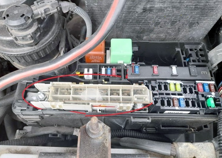
Additional elements can be attached to the back of the fuse box.
Photo – diagram

Appointment
- 1 40A AM1 – Rear differential lock system, ABS, TRC, VSC, fuses: “ACC”, “CIG”, “ECU-IG & GAUGE”, “WIP”
- 2 40A IG1 – Fuses: “PWR”, “S-HTR”, “4WD”, “DOOR”, “DEF”, “MIR HTR”
- R1 – Sockets (PWR OUT)
- R2 – Heater (HTR)
- R3 – Integrated relay
Relay box
Located behind the glove compartment and attaches to the vehicle body.
LHD

RHD

Type 1
Diagram
Decoding
| 1 | 25A DOOR – System of the electric drive of door locks and windows with electric windows |
| 2 | 20A DEF – Heated rear window and multiport fuel injection system / sequential multiport fuel injection system |
| 3 | 15A S-HTR – Heated seats |
| 4 | 20A 4WD – Rear Differential Locking System, ABS, TRC and VSC |
| 5 | 30A PWR – Power Windows |
| Relay | |
| R1 | Ignition (IG1) |
| R2 | Heated rear window (DEF) |
Type 2
Diagram

Assignment
| 1 | 15A MIR HTR – Up to November 2011: Heated exterior mirrors |
| 25A DOOR – November 2011: System of electric drive of door locks and windows with electric windows | |
| 2 | 25A DOOR – Until November 2011: System of electric door locks and windows with electric windows |
| 20A DEF – From November 2011: Heated rear window and multiport fuel injection system / sequential multiport fuel injection system | |
| 3 | 20A DEF – Up to November 2011: Heated rear window and multiport fuel injection system / sequential multiport fuel injection system |
| 15A S-HTR – From November 2011: Seat heaters | |
| 4 | 15A S-HTR – Before November 2011: Seat heaters |
| 20A 4WD – From November 2011: Rear Differential Locking System, ABS, TRC and VSC | |
| 5 | 20A 4WD – Up to November 2011: Rear Differential Locking System, ABS, TRC and VSC |
| 15A MIR HTR – From November 2011: Heated exterior mirrors | |
| R1 | Heated exterior mirrors (MIR HTR) |
| R2 | Ignition (IG1) |
| R3 | Heated rear window (DEF) |
Engine compartmen
Location
General layout of blocks in the engine compartment
LHD

RHD

Designation
- Fuse and relay box
- Brake actuator
- Headlight wiper relay
- Glow plug control unit
- 2TR-FE: Air control unit
RHD:
1KD-FTV and 2KD-FTV (no DPF): Injector Control Unit (EDU)
LHD:
1KD-FTV and 2KD-FTV (DPF): Injector Control Unit (EDU) - RHD:
1KD-FTV and 2KD-FTV (DPF): Injector Control Unit (EDU)
LHD:
1KD-FTV and 2KD-FTV (no DPF): Injector Control Unit (EDU)
Fuse and relay box
It is located on the left side of the engine compartment, next to the battery.

Diagram from the box cover

Diagram

A

Protected components
| 1 | 25A Spare fuse |
| 2 | 15A Spare fuse |
| 3 | 10A Spare fuse |
| 4 | 7,5A FOG – Fog lights |
| 15A 7,5A FOG – Fog lights | |
| 5 | 10A HORN – Sound signal |
| 6 | 25A EFI – Multiport fuel injection system / sequential multiport fuel injection system |
| 7 | – |
| 8 | 20A H-LP RL – Before June 2011: Right headlight (low beam) |
| 15A H-LP RL – From June 2011: Right headlight (low beam) | |
| 9 | 20A H-LP LL – Before June 2011: LH headlight (low beam) |
| 15A H-LP LL – From June 2011: LH headlight (low beam) | |
| 10 | 20A H-LP RH – Up to June 2011: RH headlight (high beam) and RH headlight (low beam) |
| 15A H-LP RH – From June 2011: RH headlight (high beam) and RH headlight (low beam) | |
| 11 | 20A H-LP LH – Before June 2011: LH headlight (high beam) and LH headlight (low beam) |
| 15A H-LP LH – From June 2011: LH headlight (high beam) and LH headlight (low beam) | |
| 12 | 10A EFI NO.2 – Multiport fuel injection system / sequential multiport fuel injection system |
| 13 | 10A ECU-IG NO.2 – Multiport fuel injection system / sequential multiport fuel injection system |
| 14 | 7.5A ECU-B – Before Aug 2008: Door Light Switches, Electric Door Lock System, Wireless Remote Control System, Steering Sensor and Headlights |
| 10A ECU-B – From Aug 2008: Door Light Switches, Electric Door Lock System, Wireless Remote Control System, Steering Sensor and Headlights | |
| 15 | 15A RAD – Before August 2013: Audio system |
| 20A RAD – From August 2013: Audio System | |
| 16 | 7,5A DOME – Interior lighting, engine switch lights, personal light, gauges and indicators, clock, multifunction display, wireless remote control system, daytime running light system and fog lights / rear fog lights |
| 17 | 20A A / F – Exhaust Gas Reduction System |
| 18 | 10A ETCS – Multiport fuel injection system / sequential multiport fuel injection system, electronic throttle control system |
| 19 | 7,5A ALT-S – Charging system |
| 20 | 15A TURN-HAZ – Hazard warning lights and direction indicators |
| 21 | – |
| 22 | 7,5A ECU-B NO.2 – Air conditioning system |
| 23 | 30A DCC – Fuses: “ECU-B”, “DOME”, “RAD” |
| 24 | 50A PTC NO.1 – Additional heater |
| 25 | 30A H-LP CLN – Before June 2011: Headlight cleaners |
| 30A PWR SEAT – Power Seat | |
| 26 | 50A PTC NO.2 – Additional heater |
| 30А PTC NO.2 – Additional heater | |
| 27 | 40A ABS NO.1 – Before August 2008: ABS, TRC and VSC |
| 40A H-LP CLN – From June 2011: Headlight cleaners | |
| 28 | 40A FR HTR – Before Aug 2009: Air Conditioning, Fuse: “A / C” |
| 50A FR HTR – From Aug 2009: Air Conditioning, Fuse: “A / C” | |
| 29 | 30A ABS NO.2 – ABS, TRC and VSC |
| 30 | 40A ABS NO.1 – From August 2008: ABS, TRC and VSC |
| 31 | 100A ALT – Charging system, fuses: “PWR SEAT”, “HLP CLN”, “FR HTR”, “AM1”, “IG1”, “PTC NO.1”, “PTC NO.2”, “PWR OUT”, “STOP”, “TAIL”, “OBD” |
| 32 | 80A GLOW – Engine preheating system |
| 33 | 50A BATT P / I – Fuses: “FOG”, “HORN”, “EFI” |
| 34 | 30A AM2 – Engine starter, fuses: “ST”, “IGN”, “INJ”, “MET” |
| 35 | 40A MAIN – Fuses: “H-LP RH”, “H-LP LH”, “H-LP RL”, “H-LP LL” |
| 36 | 50A A / PUMP – Multiport fuel injection system / sequential multiport fuel injection system |
| Relay | |
| R1 | Dimmer (DIM) |
| R2 | Headlights (H-LP) |
| Glow plugs (GLOW) | |
| A | |
| R1 | Starter (ST) |
| R2 | 1TR-FE, 2TR-FE, 1GR-FE: Air Fuel Ratio (A / F) Sensor |
| 1KD-FTV without DPF, 2KD-FTV without DPF, 5L-E: Glow plugs (GLOW) | |
| 1KD-FTV with DPF, 2KD-FTV with DPF: Air Fuel Ratio (A / F) Sensor | |
| R3 | 1TR-FE, 2TR-FE, 1GR-FE: Fuel pump (F / PMP) |
| 1KD-FTV with DPF, 2KD-FTV with DPF: – | |
If you have something to add – write in the comments.
 FuseAndRelay.com
I have a kun25 turbo diesel engine which I fit in into a body of wiring of kun15 and it doesn’t start at all but crank. Need really need your assistance soon.
Kenapa mobil saya tidak bisa di estarter
Dan tidak bisa berbuiny tak tak
I have a kun25 toyota hilux 2kd-ftv but the dashboard gauges doesn’t work please need advise on this for trouble shooting
Toyota hilux 2kdegine has a problem of indicators, battery sign, radio, aircon and windows are not worki
working including wipers
Please help
Where can I find the fuel pump shut off switch on a 5th element 2004 model?
Hi so iv lost power to my windows and blinkers and ac put new alternator in and new fusible link no starts but same no windows etc please help
All power windows are not working on my hilux vigo 2006, 2kd. Is it controlled by relay, if so, where is the location of the relay. I need any kind help. Thanks in advance.
I have a Toyota Hilux 2.7 2008 Model (Vigo) but my fuse ports 8 & 9 are blank with no petal contact visible inside the fuse box. Relays R1 & R2 are also missing but I can see something that looks like a relay with hardwired cables underneath. My problem right now is that my low beams are not working and I don’t have an idea where to fix them.
i also like FUSE APP
Hi, I’m working on a toyota hilux kun25 and having problem with the glow plugs light not come on . I changed the glow relay but the glow light still not working. Please could any help with the glow light?