Toyota Carina ED of the third generation was produced in 1993, 1994, 1995, 1996, 1997, 1998, 1999 with various bodies T200, T201, T202, T203, T204, T205. Toyota Exiv and Toyota Celica were produced on a common basis with this model. In this publication, we will show the locations of electronic control units, a description of fuses and relays Toyota Carina ED (Exiv / Celica) T 200 with box diagrams and photo examples of their execution. Note the cigarette lighter fuse.

Check the purpose of the elements with your diagrams on the box cover.
Contents
Passenger compartment
Location
Layout

Assignment
- air conditioner amplifier
- JC # 3
- central lock control relay
- air conditioner electronic control unit
- ABS electronic control unit
- relay box No. 1
- mounting box No. 1
- mounting block under the dashboard
- electronic engine control unit
- fuel pump relay
- deceleration sensor
- the main relay of the electric drive of the roof folding
- audio amplifier
- start inhibit switch
- relay block No. 4
- mirror control relay
- mode relay “EX-HI”
Fuse box
It is located at the bottom of the dashboard on the driver’s side, behind the protective cover.

Covery

Diagram

Designation
| 20 | 15A ECU-IG – Electronically controlled automatic transmission, anti-lock braking system |
| 21 | 20A SEAT-HTR – Heated seats |
| 22 | 7,5A PANEL – Illumination of the instrument panel |
| 23 | 15A STOP – Stop Lamps, Stop Lamp High, Multiport Fuel Injection System / Sequential Multiport Fuel Injection System, Cruise Control Cancellation Device, Electronically Controlled Automatic Transmission, Antilock Braking System |
| 24 | 20A FOG – Front fog lights |
| 25 | 15A CIG & RAD – Cigarette Lighter, Digital Clock Display, Car Audio |
| 26 | 7,5A IGN – Charging system, discharge warning lamp, multiport fuel injection system / sequential multiport fuel injection system, SRS airbag system |
| 27 | 20A WIPER – Windscreen wipers and washer, rear window wiper and washer |
| 28 | 10A MIR-HTR – Multiport fuel injection system / sequential multiport fuel injection system |
| 29 | 10A TURN – Direction indicators, emergency flashers |
| 30 | 15A TAIL – Tail lights, parking lights, front side marker lights, rear side marker lights, license plate lights |
| 31 | 10A HTR – Air conditioning, heated rear window |
| 32 | 10A GAUGE – Sensors and Counters, Power Door Lock System |
| 33 | 7,5A ST – Starting system, multiport fuel injection system / sequential multiport fuel injection system |
| 34 | 10A A / C – Air Conditioning |
| 35 | 7,5A OBD II – On-board diagnostic system |
| 38 | 40A AM1 – Electronic Ignition System / Distribution Ignition System |
| 39 | 30A DOOR – Power door locking system, convertible top control system |
| 40 | 30A DEF – Heated rear window |
| 41 | 30A POWER – Power windows, power sunroof |
The fuse number 25A for 15A is responsible for the operation of the cigarette lighter.
Some relays are attached to the back of the unit.
Scheme

Functions
- R1 – Relay dimensions
- R2 – Main power relay
- R3 – Rear window defogger relay
Numbers 34 and 35 are located separately on the left side guard, relay box 4 (heater relay).
Relay box
Diagram

Appointment
- R1 – Relay – direction indicator interrupter
- R2 –
- R3 – Fog lamp relay
- R4 –
Engine compartment
Location
Layout
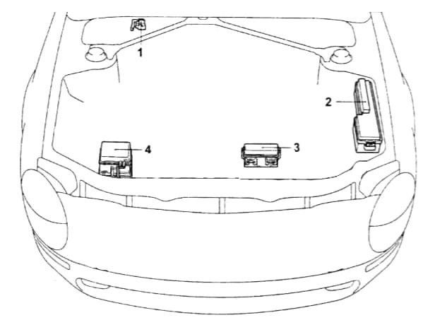
Decoding
- manifold absolute pressure sensor
- fuse and relay box
- relay box No. 6
- relay box No. 5
Fuse and relay box
Photo example

Diagram

Assignment
| 1 | 30A AM2 – Starting system |
| 2 | 10A HAZARD – Emergency flashers |
| 3 | 7,5A HORN – Signal |
| 4 | 20A RADIO No.1 – Car audio system |
| 5 | 15A ECU-B – Anti-lock braking system, cruise control |
| 6 | 10A DOME – Interior lighting, personal lighting, luggage compartment lighting, trunk lighting, door lighting, clock |
| 7 | 15A HEAD (LH) – Left headlight |
| 8 | 15A HEAD (RH) – Right headlight |
| 9 | Spare |
| 10 | Spare |
| 11 | Spare |
| 12 | 7,5A ALT-S – Charging system |
| 13 | 7,5A SRS WRN – SRS airbag warning lamp |
| 14 | 15A EFI – Multiport fuel injection system / sequential multiport fuel injection system |
| 15 | 15A HEAD (LH) LO – Left headlight (low beam) |
| 16 | 15A HEAD (RH) LO – Right headlight (low beam) |
| 17 | 15A HEAD-HI (RH) – Right headlight (high beam) |
| 18 | 15A HEAD-HI (LH) – Left headlight (high beam) |
| 19 | 7,5A DRL – Daytime Running Light System |
| 36 | 30A RDI – Electric cooling fan |
| 37 | 30A CDS – Electric cooling fan |
| 42 | 40A HTR – Air Conditioning |
| 43 | 100A ALT – Fuses “ALT-S”, “TAIL”, “DOOR”, “DEF” and “POWER” |
| 44 | 60A MAIN – Starting system, headlights, fuses “AM2”, “HAZARD”, “HORN”, “DOME” and “RADIO”. |
| 45 | 50A ABS – Anti-lock braking system |
| R1 | Relay 1 electro radiator fan |
| R2 | Main motor relay |
| R3 | Horn relay |
| R4 | Headlight relay |
| R5 | Starter relay |
| R6 | Main relay of the injection system |
Relay box 6
Diagram

Designation
- R1 – Relay of the main electric motor of the 4WS system
- R2
- R3 – Relay of the main electric motor of the 4WS system
Relay box 5
Diagram

Appointment
- R1 – ABS solenoid valve relay
- R2 – Relay 2 of the radiator fan motor
- R3 – ABS electric pump relay
- R4 – Relay 2 of the radiator fan motor
- R5 – Relay of the electromagnetic clutch of the air conditioning compressor
If you have something to add – write in the comments.