Toyota Camry 40 is the sixth generation of the Camry range and was produced in 2006, 2007, 2008, 2009, 2010, 2011. This vehicle has been delivered all over the world. Also known as Daihatsu Altis. In this publication, we will show the location of the electronic control units, a designation of fuses and relays for the Toyota Camry 40 with diagrams and photographs. Highlight the cigarette lighter fuse.

The number of elements in boxes may differ from the one presented and depends on the year of manufacture and the level of equipment. Check the description with your diagrams on the block lid.
Contents
Electronics boxes passenger compartment
Layout
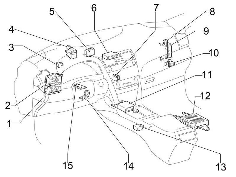
Designation
- Fuse box
- Body electrical control unit
- Turn signal relay (alarm)
- Distribution block No. 3
- ID block (vehicles with Smart System) Key transponder (vehicles without Smart System)
- Junction block (CAN)
- Distribution block No. 4
- Air conditioner amplifier
- Certification block
- Tire pressure monitor
- Central airbag unit
- Audio amplifier
- Gear selector lock block
- Key signal amplifier
- Steering lock block
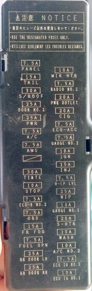
Fuse box
Installed on the left under the dashboard. The protective cover must be removed for access.

Legend from the block cover
Diagram
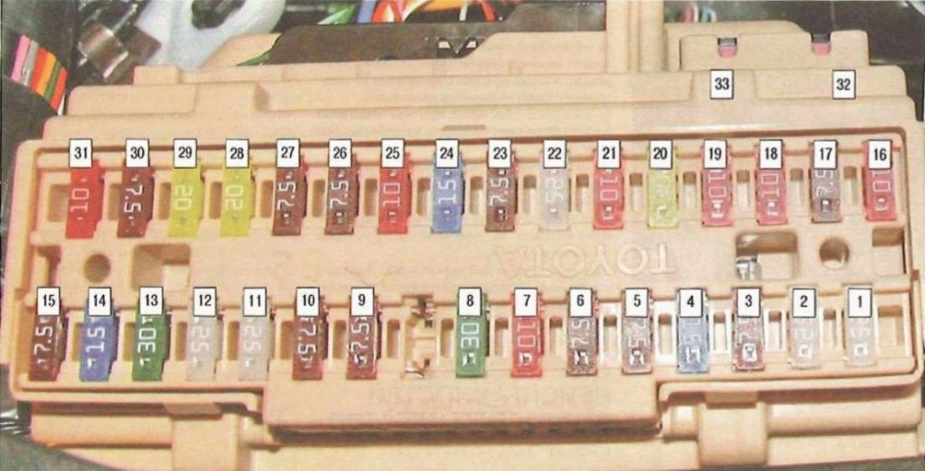
Assignment
| 1 | 25А RR DOOR RH – Rear right glass lift |
| 2 | 25А RR DOOR LH – Rear left glass lift |
| 3 | 7,5A FUEL OPN – Fuel filler flap |
| 4 | 15A FR FOG – Front fog light |
| 5 | 7.5А OBD – Diagnostic connector |
| 6 | 7,5А ECU − B NO.2 – Glass lifters |
| 7 | 10A STOP – Stop lamps, additional brake light, gear selector lock, fuel injection system, body control unit, ABS, vehicle stabilization system, traction control, brake assist system, throttle valve control system |
| 8 | 30A TI&TE – Tilt and telescopic steering |
| Reserve | |
| 9 | 7,5A AM1 – Fuel injection system |
| 10 | 7,5A A / C – Air conditioner |
| 11 | 25A PWR – Glass lifters |
| 12 | 25A DOOR NO.2 – Body ECM |
| 13 | 30A S/ROOF – Люк |
| 14 | 15A TAIL – Side light, license plate lighting, reversing lamps, front direction indicators, body control unit |
| 15 | 7,5A PANEL – Navigation, heated seats, alarm, air conditioning, audio system, clock, glove box lighting, vehicle stabilization system, traction control, instrument panel lights, steering wheel switches |
| 16 | 10A ECU IG NO.1 – Body ECU, wiper and washer, sunroof, tire pressure monitor, cooling fan, navigation, auto-dimming interior mirror |
| 17 | 7,5A ECU IG NO.2 – ABS, vehicle stabilization system, traction control, brake assist system, gear selector lock, automatic transmission, cruise control |
| 18 | 10A A / C NO.2 – Air conditioning, heated rear window |
| 19 | 10A WASH – Screen wiper and washer |
| 20 | 20A S-HTR – Heated seats |
| 21 | 10A GAUGE NO.1 – Hazard warning lights, reversing lamps, fuel injection system, battery charging system |
| 22 | 25A WIP – Screen wiper and washer |
| 23 | 7,5A H − LP LVL – Electro headlight range control |
| 24 | 15A INJ – Fuel injection system, starting system |
| 25 | 10A IGN – Fuel injection system, anti-theft system, airbags, steering lock system, front passenger classification system, throttle control system, keyless entry system |
| 26 | 7,5A GAUGE NO.2 – Instrument cluster, clock, multi-information display |
| 27 | 7.5A ECU-ACC – Clock, gear selector lock, body ECM, power mirrors, keyless entry system |
| 28 | 20A CIG – Cigarette lighter |
| 29 | 20A PWR OUTLET- Socket |
| 30 | 7,5A RADIO NO.2 – Audio system, navigation |
| 31 | 10A MIR HTR – Heated mirrors |
For the cigarette lighter and rear outlet, fuses 28 and 29 are responsible for 20A.
Fuses 32 at 30A POWER – Power windows and 33 at 30A P / SEAT – Power seats are located separately at the top of the unit.
Relay
Several relay elements are attached to the back of the unit.
Diagram

Appointment
- R1 Fog light
- R2 side light
- R3 Auxiliary relay
- R4 Window regulators
- R5 Ignition (IG1)
Electronics boxes engine compartment
Location

Diagram
- Engine control unit (2AZ-FE)
- Main fuse and relay box
- Transmission control unit
- Fan control unit
- Skid Control
- Engine control unit (2GR-FE)
Main fuse and relay box
The photo
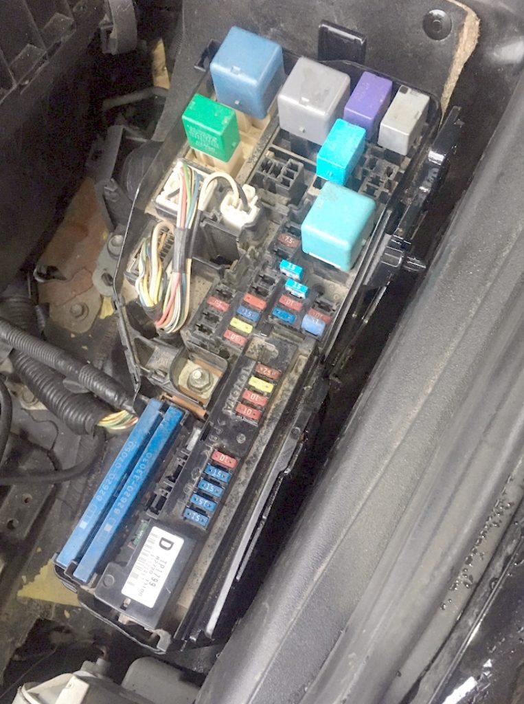
Diagram

Description
| 1 | Not used |
| 2 | 10А RR FOG – Rear fog light |
| 3 | 15A FR DEF – Front fog light |
| 4 | Not used |
| 5 | 7,5А AM2 – Starting system |
| 6 | 7,5А ALT − S – Battery charging system |
| 7 | 7,5А MAYDAY / TEL – Phone |
| 8 | – |
| 9 | 30A EFI2 – 2AR-FE (2009-2011): Fuel injection system |
| 10 | 10А E ACM – 2GR-FE: – |
| 11 | 10A ETCS – Throttle Control System |
| 12 | 15А HAZ – Direction indicators, instrument cluster |
| 13 | 20A IG2 – Fuel injection system, starting system, fuses: GAUGE NO.2, IGN, INJ |
| 14 | 20А STR LOCK – Steering lock system |
| 15 | 10A DOME – Instrument cluster, vanity mirror illumination, luggage compartment illumination, ignition switch illumination, door illumination, interior illumination, clock, reading lamps, keyless entry system |
| 16 | 10А ECU − B NO.1 – Wireless remote control system, body electrical control unit, vehicle stabilization system, front passenger classification system |
| 17 | 15А RADIO NO.1- Audio system, navigation |
| 18 | 25A DOOR NO.1 – Body electrical control unit |
| 19 | – |
| 20 | 25А AMP – Audio system |
| 21 | 30A EFI MAIN – Fuel injection system, throttle valve control system, body electrical control unit, fuses: “EFI NO.2” and “EFI NO.3” |
| 22 | Not used |
| 23 | 10A EFI NO.3 – Fuel injection system |
| 24 | 15A EFI NO.2 – Fuel injection system |
| 25 | 7.5А S − HORN – Sound signal |
| 26 | 20A A / F – Fuel injection system |
| 27 | 10A MPX − B – Instrument cluster |
| 28 | 10A EFI NO.1 – Anti-theft system, keyless entry system, fuel injection system, throttle control system |
| 29 | 10А HORN – Sound signal |
| 30 | 15А H − LP (RL) – Low beam right |
| 31 | 15А H − LP (LL) – Low beam left |
| 32 | 15А H − LP (RH) – High beam right |
| 33 | 15А H − LP (LH) – High beam left |
| 34 | 50A HTR – Air Conditioning |
| 35 | 50А ABS NO.1 – ABS, vehicle stabilization system, traction control, brake assist system |
| 36 | 50A FAN MAIN – 2GR-FE: Engine cooling fans |
| 37 | 30А ABS NO.2 – ABS, vehicle stabilization system, traction control, brake assist system |
| 38 | 50A RR DEF – Heated rear window, fuse: “MIR HTR” |
| 39 | 30A RR PWR SEAT – Power rear seats |
| 40 | 30А H − LP CLN – Headlight washer |
| 41 | 40A CDS FAN – 2AR-FE: Engine cooling fans |
| 42 | 40A RDI FAN – 2AR-FE: Engine cooling fans |
| 43 | 30А MSB – |
| 44 | 120А ALT – FUSES: “RR FOG”, “FR DEF”, “AM2”, “ALT−S”, “MAYDAY/TEL”, “E−ACM”, “ETCS”, “HAZ”, “IG2”, “STR LOCK”, “DOME”, “ECU−B NO.1”, “RADIO NO.1”, “EFI MAIN”, “AMP”, “DOOR NO.1”, “EFI NO.3”, “EFI NO.2”, “S−HORN”, “A/F”, “MPX−B”, “EFI NO.1”, “HORN”, “H−LP(RL)”, “H−LP(LL)”, “H−LP(RH)”, “H−LP(LH)”, “HTR”, “ABS NO.1”, “FAN MAIN”, “ABS NO.2”, “RR DEF”, “RR PWR SEAT”, “H−LP CLN”, “CDS FAN”, “RDI FAN”, “MSB”, “ALT” и “ST/AM2” |
| 45 | – |
| 46 | – |
| 47 | – |
| 48 | 30A ST / AM2 – Starter, fuses: GAUGE NO.2, IGN, INJ |
| R1 | Vehicle stabilization system (VSC No.2) |
| R2 | Vehicle stabilization system (VSC No.1) |
| R3 | 2AZ-FE: Cooling fan (No.1) |
| R4 | 2AZ-FE: Cooling fan (No.3) |
| R5 | 2AZ-FE: Cooling fan (No.2) |
| 2GR-FE: Cooling fan | |
| R6 | Starter |
| R7 | Ignition |
| R8 | Air Conditioning Compressor Clutch (MGC) |
| R9 | Starter interrupt relay |
| R10 | Heated rear window |
Separately, outside the unit, additional cooling fan relays can be installed.
If you find a mistake or add something – write in the comments.
I have a 2010 Toyota Camry 4 cyl fuel pump is not getting power I having problems locating the fuel pump relay
I’m having the same problem with my 2009 Camry. Have you located it, and can you tell me if you know.
Fuel pump relay (C/OPN Relay) is in the junction block that has fuses number 25-33. The junction block is attached to the fuse box housing.
Where is the headlight relay?
Where is the 2010 Camry Headlight Relay location?
which is the headLamp relay in the fuse box?
Please anyone, where is the headlight relay?
Were is location etc fuse
اريد صوره قاعده فيوزات كامري 2012 وارد امريكي