Toyota Avensis 2nd generation has the code T25 / T250 and was produced in 2003, 2004, 2005, 2006, 2007, 2008 and 2009. In this article you will find information with the locations of all electronic control units, a detailed description of fuses and relays Toyota Avensis 2 with fuse box diagrams and photo examples of their execution. Separately, we highlight the cigarette lighter fuse.

The design of the units and their arrangement may differ from the one shown and depend on the year of manufacture, the level of equipment and the region of delivery.
Contents
Passenger compartment
Location
General layout of electronic control units in the cabin
LHD

RHD

Designation
- Fuse box
- Integrated relay
- Fuel Pump Relay (Circuit Opening)
- Rear fog light relay
- Heated rear window relay
- Relay box
- Turn signal relay
- Key transponder amplifier
- EPS ECU
- Key transponder control unit
- Antenna amplifier
- Distribution block
- Wiper relay
- Central locking receiver
- Headlight range control unit
- Engine and transmission control unit (A / T) / Engine control unit (M / T)
- Air conditioner control unit
- Optional connector (navigation)
- Gear selector control unit
- Airbag control unit
- Navigation control unit
- Additional fuse box
- RHD: Anti-theft control unit
Fuse box
It is located at the bottom of the dashboard behind a protective cover.
Photo – example

Diagram
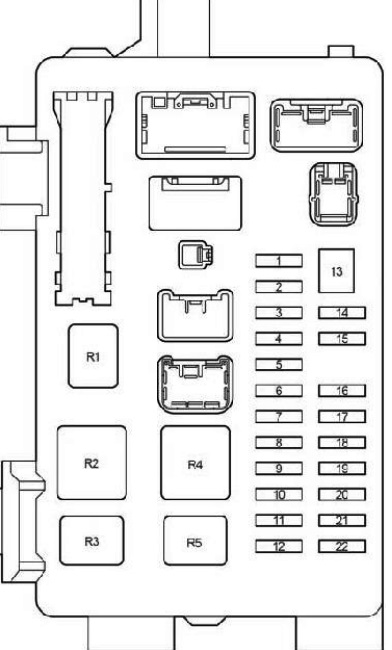
Assignment
| 1 | 10A IGN – SRS airbags, instrument cluster, starting system, multiport fuel injection system / sequential multiport fuel injection system |
| 2 | 20A S / ROOF – Hatch |
| 3 | 7,5A RR FOG – Rear fog light |
| 4 | 15A FR FOG – Front fog light, fog light indicator |
| 5 | 25A AM1 – Starting system, fuses: “CIG”, “RAD NO.1” |
| 6 | 7,5A PANEL – Instrument panel illumination, instrument cluster illumination, automatic transmission control unit, glove compartment illumination, armrest compartment illumination, headlight wipers, front fog light, parking aid, multi – information display |
| 7 | 20A RR WIP – Rear wiper and washer |
| 8 | 7,5A GAUGE2 – Reversing lamps, headlight range control, direction indicators, hazard warning lights |
| 9 | 15A CIG – Cigarette lighter |
| 10 | 10A HTR – Heated seats, air conditioning |
| 11 | – |
| 12 | 7,5A RAD NO.1 – Audio system, multi-information display, power mirrors, instrument cluster, socket |
| 13 | 30A PWR SEAT – Power Seats |
| 14 | 10A TAIL – Side light, license plate light, luggage compartment light, automatic light system, front fog light, rear fog light, instrument cluster |
| 15 | 7,5A OBD2 – Diagnostic connector |
| 16 | 15A P / POINT – Socket |
| 17 | 25A DOOR – Central locking |
| 18 | 25A WIP – Front wiper and washer, headlight wipers |
| 19 | 7,5A ECU-IG – Cooling Fan, Charging System, Power Steering, ABS, VSC |
| 20 | 20A S-HTR – Heated seats |
| 21 | 10A GAUGE1 – Light switch, multi – information display, integrated relay, instrument cluster, gear selector lock, automatic transmission control unit, rearview mirror, wiper, parking brake |
| 22 | 15A STOP – Stop lamps, gear selector lock, auxiliary brake light, multiport fuel injection system / sequential multiport fuel injection system |
| Relay | |
| R1 | Reserve |
| R2 | HTR – Heater |
| R3 | SEAT HTR – Heated seats |
| R4 | IG1 – Ignition |
| R5 | TAIL – Side light |
The fuse number 9 at 15A is responsible for the operation of the cigarette lighter.
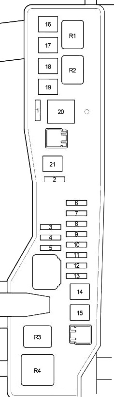
Additional fuse box
Located above the pedals, parallel to the floor.

Diagram

Circuits protected
| 1 | – |
| 2 | 20A P-RR P / W – Window regulator |
| 3 | 20A P-FR P / W – Window regulator |
| 4 | 20A D-RR P / W – Window Regulator |
| 5 | 20A D-FR P / W – Window regulator |
| 6 | 7,5A ECU-B 1 – Gearbox |
| 7 | 10A FUEL OPN – Fuel filler flap |
| 8 | 20A FR DIC – Heated area of windscreen wiper blades, fuse: “MIR HTR” |
| 9 | – |
| 10 | 7,5A DEF I / UP – Air conditioner |
| 11 | 7,5A ST – Multi – information display, multiport fuel injection system / sequential multiport fuel injection system, starting system |
| 12 | 10A MIR HTR – Heated mirrors |
| 13 | 15A RAD NO.2 – Audio system, multi – information display |
| 14 | 7,5A DOME – Interior lighting, personal lighting, door lighting, luggage compartment lighting, individual mirror lighting, footwell lighting |
| 15 | 7,5A ECU-B 2 – Air conditioning, wireless control system |
| 16 | 30A PWR SEAT – Power Seats |
Relay box
Diagram
LHD

RHD

Decoding
- R1 – Heated area of windscreen wiper blades (FR DEICER)
- R2 – Socket (P / POINT)
- R3 – Front fog light (FR FOG)
- R4 – Starter (ST)
Additional elements
Diagram

Appointment
- Phone Microphone Amplifier
- Sunroof control unit
- Rear wiper relay
Engine compartment
Location
General layout of electronic control units under the hood
Type A
(1AZ-FSE, 1AZ-FE, 1ZZ-FE, 3ZZ-FE)

Type B
(1CD-FTV)

Description
- Injector control unit
- Additional fuse box
- Fuse and relay box
- Left headlight control unit
- Relay box
- Headlight wiper relay
- Right headlight control unit
- Brake control unit (VSC)
- Brake control unit (without VSC)
- Glow plug relay
- Auxiliary heater
Fuse and relay box
Located on the left side of the engine compartment.

Diagram
Type A

Type B
Assignment
| 1 | – |
| 2 | 25А VSC – 1CD-FTV: ABS, VSC |
| 25A ABS – 1CD – FTV: ABS | |
| 3 | – |
| 4 | – |
| 5 | – |
| 6 | 7,5A ALT-S – Charging system |
| 7 | 30A DCC – Fuses: “ECU-B NO.2”, “DOME”, “RAD NO.2” |
| 8 | 30A AM2 – Starting system, fuses: “ST”, “IGN” |
| 9 | 10A HAZARD – Direction indicators, hazard warning lights |
| 10 | 25A F-HTR – 1CD-FTV: Fuel heating |
| 11 | 15A HORN – Sound signal |
| 12 | 20A EFI – Multiport fuel injection system / sequential multiport fuel injection system, fuses: “EFI NO.1”, “EFI NO.2” |
| 13 | 25A PWR HTR – 1CD – FTV: Auxiliary heater |
| 14 | 30A RR DEF – Heated rear window |
| 15 | 40A MAIN – Headlight cleaners, headlights, fuses: “H-LP HI LH”, “H-LP HI RH”, “H-LP LH”, “H-LP RH” |
| 16 | 50A AM1 NO.1 – 1CD-FTV: fuses: “ACC”, “CIG”, “RAD NO.1”, “ECU-B NO.1”, “FL P / W”, “FR P / W”, “RL P / W”, “RR P / W” |
| 17 | 30A H / CLN – Headlight cleaners |
| 18 | 40A HTR – Air Conditioning. heater |
| 19 | 30A CDS – Cooling fan |
| 20 | 40A RDI – 1CD-FTV, 1ZZ-FE, 3ZZ-FE: Cooling fan |
| 30A RDI – 1AZ-FE, 1AZ-FSE: Cooling fan | |
| 21 | 50A VSC – 1CD – FTV: ABS, VSC |
| 40A ABS – 1CD – FTV: ABS | |
| 22 | 15A IG2 – 1AZ-FSE, 1AZ-FE, 1ZZ-FE, 3ZZ-FE: Starting system, multiport fuel injection system / sequential multiport fuel injection system |
| 23 | 10A THROTTLE – 1AZ-FSE, 1AZ-FE, 1ZZ-FE, 3ZZ-FE: Electronic throttle control system |
| 10A ETCS – 1AZ-FSE, 1AZ-FE, 1ZZ-FE, 3ZZ-FE: Electronic throttle control system | |
| 24 | 20A A / F – 1AZ-FSE, 1AZ-FE: Air-fuel ratio sensor |
| 25 | 1AZ-FSE, 1AZ-FE, 1ZZ-FE, 3ZZ-FE: – |
| 26 | 1AZ-FSE, 1AZ-FE, 1ZZ-FE, 3ZZ-FE: – |
| 27 | 50A EMPS – 1ZZ-FE, 3ZZ-FE: Power steering |
| Relay | |
| R1 | EFI MAIN – 1CD – FTV: Cooling fan |
| R2 | EDU – 1CD – FTV: Cooling fan |
| R3 | FAN NO.3 – 1CD – FTV: Cooling fan |
| R4 | FAN NO.1 – Cooling fan |
| R5 | FAN NO.2 – 1AZ-FSE, 1AZ-FE, 1ZZ-FE, 3ZZ-FE: Cooling fan |
| R6 | 1AZ-FSE, 1AZ-FE, 1ZZ-FE, 3ZZ-FE: – |
| R7 | FAN NO.3 – 1AZ-FSE, 1AZ-FE, 1ZZ-FE, 3ZZ-FE: Cooling fan |
| R8 | 1AZ-FSE, 1AZ-FE, 1ZZ-FE, 3ZZ-FE: – |
| R9 | EMPS – 1ZZ-FE, 3ZZ-FE: Power steering |
Additional fuse box
Diagram
Type A

Protected components
| 1 | – |
| 2 | 50A HTR2 – Auxiliary heater |
| 3 | 50A HTR1 – Auxiliary heater |
| 4 | 80A GLOW – Glow plugs |
| 5 | 140A ALT – Relay: “IG1”, “TAIL”, “SEAT HTR”, fuses: “H-LP CLN”, “AM1 NO.1”, “RDI”, “CDS”, “VSC” (50A), ” VSC “(25A),” ABS “(40A),” ABS “(25A),” H / CLN “,” RR DEF “,” GLOW “,” HTR NO1 “,” HTR NO2 “,” RFGHTR “,” AM1 NO.2 “,” RR FOG “,” S / ROOF “,” STOP “,” P / POINT “,” FR FOG “,” OBD2 “,” DOOR “ |
| Relay | |
| R1 | |
| R2 | HTR2 – Auxiliary heater |
| R3 | HTR1 – Auxiliary heater |
Type B

Designation
| 1 | 10A EFI NO.1 – Multiport fuel injection system / sequential multiport fuel injection system |
| 2 | 7,5A EFI NO.2 – Emission control system |
| 3 | 25A VSC – ABS, VSC |
| 25A ABS – ABS | |
| 4 | 100А ALT – 1ZZ-FE, 3ZZ-FE: Fuses: “AM1 NO.1”, “H-LP CLN”, “ABS” (25A), “VSC” (25A), “ABS” (40A), “VSC “(50 A),” CDS “,” RDI “,” HTR “,” RR DEF “,” RR FOG “,” FR FOG “,” AM1 “,” DOOR “,” STOP “,” OBD2 “,” S / ROOF “,” PWR SEAT “,” P / POINT “,” TAIL “,” PANEL “,” RR WIP “,” ECU-IG “,” WIP “,” GAUGE2 “,” GAUGE1 “,” HTR ” , “S-HTR” |
| 120А ALT – 1AZ-FSE, 1AZ-FE: Fuses: “AM1 NO.1”, “H-LP CLN”, “ABS” (25A), “VSC” (25A), “ABS” (40A), “VSC “(50 A),” CDS “,” RDI “,” HTR “,” RR DEF “,” RR FOG “,” FR FOG “,” AM1 “,” DOOR “,” STOP “,” OBD2 “,” S / ROOF “,” PWR SEAT “,” P / POINT “,” TAIL “,” PANEL “,” RR WIP “,” ECU-IG “,” WIP “,” GAUGE2 “,” GAUGE1 “,” HTR ” , “S-HTR” | |
| 5 | 50A VSC – ABS, VSC |
| 40A ABS – ABS | |
| 6 | 50A AM1 NO.1 – Fuses: “PWR SEAT”, “FR DIC”, “FUEL OPN”, “ECU-B 1”, P-RR P / W “,” P-FR P / W “,” D- RR P / W “,” D-FR P / W “ |
| 7 | 30A H-LP CLN – Headlight cleaners |
| Relay | |
| R1 | INJ – Injector |
| R2 | EFI – Engine control unit |
| R3 | IG2 – Ignition |
| R4 | A / F – Air-fuel ratio sensor |
Relay box
Photo – example

Diagram

Assignment
| 1 | 10A H-LP HI LH – Left headlight (high beam) |
| 2 | 10A H-LP HI RH – Right headlight (high beam), instrument cluster |
| 3 | 15A H-LP LH – Left headlight (low beam) |
| 4 | 15A H-LP RH – Right headlight (low beam) |
| Relay | |
| R1 | HORN – Sound signal |
| R2 | F-HTR – Fuel heating |
| R3 | H-LP – Headlights |
| R4 | DIM – Dimmer |
| R5 | FAN NO.2 – Cooling fan |
On our YouTube channel, we also posted a video. Watch and subscribe.
If you have something to add – write in the comments.
Looking for the position charging fuse in a toyota avensis t 180 d cat d 4 d 2008 , it blew when on the battery booster , belived to be 140 amp .
2005-ös évjáratu 2.4es benzines automata combi.Világít azABS nem műkődik a seb. mérő! TOYOTA szerviz két autójavító sem tudta megcsinálni.
mechanikus részek rendben vannak és az alsó csatlakozók is.
segítsen ha tud.Köszönettel puska zoltán.
Looking for fuse for climate control actuators so I can try and re set can you advise please.
Toyota avensis 54 year diesel
Hi, I’m looking to know if my Toyota Avensis t27 Terra model 2.0 d4d Jan 2011 has a cruise control relay/fuse location as I am looking at adding the CC feature to my car.
Thank you in advance.
Bill