The compact car Renault Fluence was presented in 2009. Years of release: 2010, 2011, 2012, 2013, 2014, 2015, 2016, 2017, 2018, 2019. During this period, the Fluence model has been restyled twice. The exterior has changed a lot. We provide complete information on fuses and relays Renault Fluence. We will show where the boxes are located, their photographs and diagrams with a description of the purpose, as well as separately highlight the cigarette lighter fuse.

Deviations in the presented material and your box are possible. The manufacturer can make changes depending on the electrical equipment, engine and year of manufacture of the car.
Contents
Engine compartment
Fuse box
Located next to the rack and covered with a protective cover (communications section). How to open, you can see in the picture.

The photo

Diagram

Designation
- 10A – Side light (right headlamp, right tail light, headlamps), license plate lights, cigarette lighter lights, power window switch lights, audio system, navigation system control unit, lights of switches and switches on the instrument panel
- 10A – Side light (left headlamp, left rear lamp), left lamp on the tailgate
- 15A – Headlight washer pump
- 20A – Fog lights
- 10A – High beam (left block headlamp)
- 10A – High beam (right headlamp)
- 15A – Diagnostic socket, rear window heating relay, automatic transmission mode selector, electric headlight corrector, gas discharge lamp control unit, auxiliary heater control unit, speed limiter, automatic parking brake, automatic parking control unit, dimmable mirror in the passenger compartment
- 30A – to the ABS, ESP control unit
- 30A – Front wiper
- 10A – Airbag control unit
- 20A – Not used
- 7,5A – Automatic gearbox control unit
- 25A – Engine management system
- 15A – Oxygen concentration sensors – heating
- 20A – Automatic gearbox control unit
- 5A – Braking signals, electrical control unit, electric power steering
- 10A – Automatic gearbox operating modes sensor, electro-corrector of headlights, reversing light relay
- 15A – Electrical equipment control unit
- 30A – Starter
- – Not used
- 20A – Fuel module, ignition coils
- 10A – Electromagnetic clutch of the air conditioner compressor
- 5A – ECU injection system
- 20A – Low beam (left headlight), electrocorrector
- 20A – Low beam (right headlight), electrocorrector
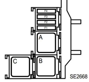
Additional box
It is located in the junction box in the engine compartment under the protection and switching unit.

Diagram

Designation
- A – Not used
- B – Fuel heater relay (450)
- C – Reverse light relay (602)
- D – Not used
- F1 – 80A heater interface unit (1550)
- F2 – 70A block preheating (257)
- F3 – 50A Transmission ECU (119)
- F4 – 80A heater interface unit (1550)
- F5 – 60A Electric fan (188) via high speed relay of the electric fan (234)
- F6 – 20A Fuel heater (449)
- F7 – Not used
- F8 – 30A – Electric fan relay control (234)
- F9 – Not used
Box near the battery

Battery disconnect unit (1)
Diagram

Assignment
- F1 – 190A Starter
- F2 – 50A fuse and relay box in the passenger compartment
- F3 – 80A fuse and relay box (control and switching unit) in the engine compartment 1, fuse and relay box in the passenger compartment
- F4 – 300A / 190A engine compartment fuse and relay box 2 / alternator
- F5 – 80A electric power steering
- F6 – 35A electronic engine control unit (ECU) / fuse and relay box (control and switching unit) in the engine compartment 1
- F7 – 5A fuse and relay box (control and switching unit) in the engine compartment 1
High Power Fuse Box (2)
The photo

Diagram

Appointment
- 70A – additional heater of the passenger compartment
- 80A – fuse and relay box in the passenger compartment
- 80A – fuse and relay box in the passenger compartment
- 80A – fuse and relay box (control and switching unit) in the engine compartment 1, fuse and relay box in the passenger compartment
- 30A – additional heater
- 50A – ABS ECU with ESP
The relay for the electric fan of the engine cooling system can be located separately, next to the electric fan itself.
Passenger compartment
Mounting box
It is located on the left side of the steering wheel, behind the cover.
Access
 Diagram

Circuits protected
| F1 | reserve |
| F2 | reserve |
| F3 | 10A cigarette lighter |
| F4 | 10A rear socket |
| F5 | 10A socket in the luggage compartment |
| F6 | 10A audio system |
| F7 | 5A electric heated exterior mirrors |
| F8 | 10A windshield washer, door open indicator |
| F9 | 30A automatic parking brake |
| F10 | 10A instrument panel |
| F11 | 25A power seat, steering column switches |
| F12 | 20A electric heated passenger seat |
| F13 | reserve |
| F14 | 25A electric window regulator for the front passenger door |
| F15 | 5A brake light switch, brake pedal position sensor, ABS / ESP control unit |
| F16 | 25A electric window regulator of the right rear door |
| F17 | 25A electric window regulator of the left rear door |
| F18 | 10A glove compartment lamp, left luggage compartment lamp, door lamps, sun visor mirror lamps, rain sensor |
| F19 | 10A clock, outside temperature indicator, seat belt warning indicator, audio system connector |
| F20 | 5A air conditioning control unit |
| F21 | 3A mirror lamps in sun visors |
| F22 | 3A interior lampshades, rain and light sensor |
| F23 | 20A trailer connector |
| F24 | 15A rear wiper |
| F25 | 3A interior rearview mirror |
| F26 | 30A 10A navigation system, CD changer, audio system |
| F27 | 20A audio system, parking brake control unit |
| F28 | reserve |
| F29 | reserve |
| F30 | 15A direction indicators |
| F31 | 10A instrument panel |
| F32 | 30A electric window regulator driver’s door |
| F33 | 25A central locking |
| F34 | reserve |
| F35 | 15A clock, outdoor temperature gauge, phone display |
| F36 | 15A diagnostic socket, horn relay, alarm control unit, siren |
| F37 | 10A brake signals, ECU |
| F38 | 30A automatic parking brake |
| F39 | reserve |
| F40 | 40A air conditioning fan |
| F41 | 25A electric sunroof |
| F42 | 40A rear window heating |
- RA 70А – power relay (+ battery) with delayed shutdown (without power off at startup)
- RB 70A – power relay (+ battery) with delayed shutdown (with power off at startup)
- RC 40C – Heated rear window relay
- RD 20A – horn relay
Cigarette lighter fuse
The fuse number 3 is responsible for the front cigarette lighter, and the rear outlet is 4 rated at 10A.
Additional elements
Box 1
Located in the passenger compartment, in the lower left part of the dashboard, on the side of the steering column.
Diagram
Designation
- F1 – 40A power supply fuse for power window relay (703), child safety relay control (750)
- F2 –
- F3 –
- F4 –
- A – 40A Power window relay
- B – 40A Rear power window child restraint relay (750)
- C – 70A 2 relays “+” with the engine running (1616) for powering the passenger compartment fan
Front seat heating relay
This relay box is located under the passenger seat: 40A relay “+” with the engine running to power the driver and passenger seat heating elements.
Also We have posted a video on our YouTube channel. Watch and subscribe.
its not match with 2013 year models
please any you helps me
Can someone tell me where the fuse location for boot on a Fluance 2010 is located please as boot lid wont open
Hi thanks for your let me go and try.
on my Renault fluence 2011 the central locking is making a sound while driving, like its opening and closing.
Also my break light, ABS is on. Break light on even when the car is off.
Hi,
My car is fluence 2017 with gearbox and is not automatic. I have problem to open the fule tank door everywhere and at fule station. Could you please help me. Whether this problem relates to its fuse fault or not? What is its fuse number and where it is?
Thanks.