Renault Duster – belongs to the class of crossovers. It was first introduced to the European market back in 2009. Years of production 2010, 2011, 2012, 2013, 2014, 2015, 2016, 2017, 2018, 2019, 2020, 2021 and up to the present. In some countries it is known as Dacia Duster. During this period, the car was restyled. We present a designation of Duster fuse boxes and relays with two basic versions (pre and restyled versions). We will show the box diagrams, the purpose of their elements, note the fuse responsible for the cigarette lighter.

Please note that the number of fuses and relays, as well as the box diagrams themselves, may differ from this material and depend on the electrical equipment, year of manufacture and country of delivery of the car.
Location of boxes with fuses and relays in the Duster:
- On the left side at the end of the instrument panel.
- In the engine compartment, just behind the battery.

Contents
Type 1
Engine compartment
Diagram

Designation
| F1 | Not used |
| F2 | Not used |
| F3 (25) | Chains: fuel pump and ignition coils; main relay K5 engine management system |
| F4 (15) | A / C Compressor Electromagnetic Clutch Circuit |
| F5 (40) | Power circuits: low speed relay of the cooling fan |
| F6 (60) | Chains protected by fuses F9, F10, F28, F29, F30, F31, F32, F36 of the mounting block 1 in the passenger compartment |
| F7 (60) | Chains protected by fuses F13, F14, F15, F16, F17, F18, F19, F20, F24, F26, F27, F37, F38, F39 of the mounting block in the passenger compartment |
| F8 (60) | Chains protected by fuses F1, F2, F3, F4, F5, F11, F12 of the mounting block in the passenger compartment |
| F9 (25) | Live circuits in position S and A of the ignition key |
| F10 (80) | Power circuits of the relay for turning on the electric heater of the passenger compartment |
| F11 (50) and F12 (25) | ABS Control Unit Chains |
Relay designation
- K1 – Relay high speed cooling fan
- K2 – Air conditioner relay
- KZ – Relay of low speed of the fan of the cooling system
- K4 – Relay of the fuel pump and ignition coils
- K5 – The main relay of the engine control system
- K6 – Not used
- K7 – Fog lamp relay. If it is not, then the PTF is not installed.
- K8 – Heater fan relay
Other versions of this block.
Passenger compartment
Located at the end of the dashboard on the driver’s side behind the cover.
Diagram

Assignment
| F1 (20) | Chains: windshield wiper; winding relay for heated glass tailgate |
| F2 (5) | Chains: power supply of the instrument cluster; windings of the K4 relay of the fuel pump and ignition coils; at the power supply of the ECU of the engine control system from the ignition switch; |
| F3 (10) | Brake light circuits |
| F4 (10) | Chains: turn signal lamps; diagnostic connector of the engine management system (pin 1); immobilizer coils; switching unit |
| F5 (5) | Rear gear electromagnetic clutch control circuit |
| F6 | Reserve |
| F7 | Reserve |
| F8 | Reserve |
| F9 (10) | Circuit of a low beam lamp of the left headlight unit |
| F10 (10) | Circuit of a low beam lamp of the right headlamp |
| F11 (10) | Chains: lamps of a high beam of the left headlight unit; headlight high beam indicator in the instrument cluster |
| F12 (10) | Circuit of a lamp of a high beam of the right block of headlights |
| F13 (30) | Rear door power window chains |
| F14 (30) | Chains of the electric windows of the front doors |
| F15 (10) | ABS control unit circuit |
| F16 (15) | Driver and front passenger seat heating circuits |
| F17 (15) | Beep circuits |
| F18 (10) | Chains: side light bulbs of the left headlamp; side light bulbs left rear light |
| F19 (10) | Chains: side light bulbs of the right headlamp; side light lamps for the right rear light; license plate lighting lamps; glove box lamps; illumination of the instrument cluster and controls on the instrument panel, console and floor tunnel lining |
| F20 (7.5) | Rear Fog Lamp Circuit |
| F21 (5) | Chains of heating elements of external rear-view mirrors |
| F22 | Reserve |
| F23 | Reserve |
| F24 (5) | Power steering control circuit |
| F26 (5) | Airbag control unit circuit |
| F27 (20) | Chains: parking sensors; reversing light bulbs; windshield washer and tailgate glass |
| F28 (15) | Chains: lamps of the interior lighting plafond; luggage compartment lamp; head unit illumination lamps |
| F29 (15) | Chains: intermittent operation of the windshield wiper; turn signal switch; alarm switch; central lock control; buzzer; diagnostic connector of the engine management system |
| F30 (20) | Central locking chains |
| F31 (15) | Fog lamp chain |
| F32 (30) | Power circuit of the relay for heating the glass of the luggage compartment |
| F33 | Reserve |
| F34 (15) | Rear gear electromagnetic clutch circuit |
| F35 | Reserve |
| F36 (30) | Power circuit of relay K8 heater fan |
| F37 (5) | Chains of electric drives of external rear-view mirrors |
| F38 (15) | Renault duster cigarette lighter; power supply of the head unit of sound reproduction from the ignition switch |
| F39 (10) | Heating, air conditioning and ventilation motor relay |
The fuse number 38 is responsible for the cigarette lighter.
Separately, under the anti-theft device, along the dashboard beam, there can be a relay for an additional heater of the passenger compartment (1067 – 1068), and under the instrument panel, a relay for heating the rear window (235).
Type 2
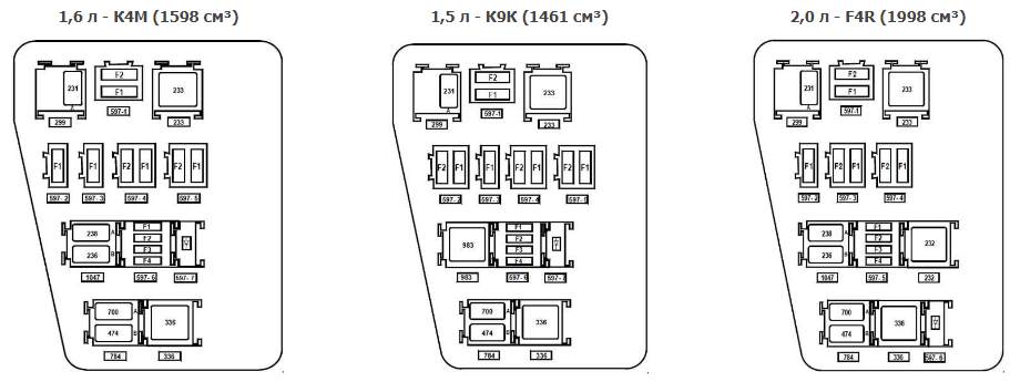
Engine compartment
The photo

Diagram

Circuits protected
| Ef1 | 10A Fog lights |
| Ef2 | 7.5A Electrical control unit |
| Ef3 | 30A Heated rear window, heaters outside mirrors |
| Ef4 | 25A Stability control unit |
| Ef5 | 60A Fuse chains P11, P24-P27, P34, P39, P41 |
| Ef6 | 60A Ignition switch (lock), P28 fuse circuits. P31, P38, P43, P46, P47 |
| Ef7 | 50A Stability control unit |
| Ef8 | 80A Luggage compartment socket |
| Ef9 | 20A Reserve |
| Ef10 | 40A Heated windshield 1 |
| Ef11 | 40A Heated windscreen 2 |
| Ef12 | 30A Starter |
| Ef13 | 15A Reserve |
| Ef14 | 25A Electronic engine management system |
| Ef15 | 15A A / C compressor clutch relay, A / C compressor clutch |
| Ef16 | 50A Electro cooling fan |
| Ef17 | 40A Automatic gearbox control unit |
| Ef18 | 80A Electric power steering pump |
| Ef19 | Reserve |
| Ef20 | Reserve |
| Ef21 | 15A Oxygen concentration sensors, canister purge valve, camshaft position sensor, phase change valve |
| Ef22 | Electronic engine control unit (ECU), electric cooling fan control unit, ignition coils, fuel injectors, fuel pump |
| Ef23 | Fuel pump |
Relay
- 20A Er1 – Horn relay
- 20A Er2 – Alarm horn relay
- 35A Er3 – Starter relay 1
- 35A Er4 – Main relay of the engine management system
- 20A Er5 – Air conditioning compressor clutch relay
- 20A Er6 – Fuel pump relay
- 35A Er7 – Heated windshield relay 2 / Electric cooling fan relay
- 35A Er8 – Heated windshield relay 1
- 20A Er9 – Starter relay 2
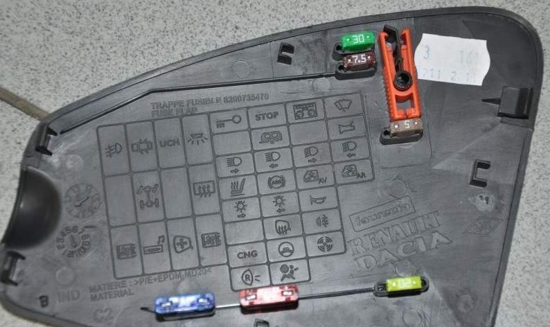
Passenger compartment
the photo

Diagram
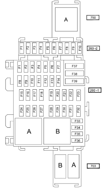
Pinout of fuses for 260-2
- Reserve
- 25A – Electrical equipment control unit, left headlight block, right headlight block
- 5A – All-wheel drive transmission (4WD)
- Reserve / 15A Additional control unit for electrical equipment
- 15A Connector for connecting additional equipment at the back ( socket )
- 5A – Electrical equipment control unit
- Reserve
- 7.5A – No data
- Reserve
- Reserve
- Relay A – Rear power window lock
Pinout 260-1 (main board)
- 30A – Power window front door
- 10A – High beam of the left headlight
- 10A – High beam of the right headlight
- 10A – Low beam of the left headlight
- 10A – Low beam of the right headlight
- 5A – Rear lights
- 5A – Front parking lights
- 30A – Power window rear door
- 7.5A – Rear fog lamp
- 15A – Sound signal
- 20A – Automatic door lock
- 5A – ABS systems – ESC, brake light switch
- 10A – Plafond lighting, luggage compartment lighting, glove compartment lighting
- Not used
- 15A – Windshield wiper
- 15A – Multimedia system
- 7,5A – Fluorescent lamps
- 7.5A – Stop light
- 5A – Injection system, instrument panel, central electronic switching unit in the cabin
- 5A – Airbag
- 7.5A – All-wheel drive transmission with 4 driving wheels (4WD), reverse gear
- 5A – Power steering
- 5A – Speed controller / limiter, rear window relay, seat belt not fastened signal, parking distance control system, relay for additional heating of the passenger compartment
- 15A – UCH (passenger compartment central electronic switching unit)
- 5A – UCH (passenger compartment central electronic switching unit)
- 15A – Direction indicators
- 20A – Steering column switches
- 15A – Sound signal
- 25A – Steering column switches
- Not used
- 5A – Instrument panel
- 7,5А – Radio receiver, control panel for cabin air conditioning, interior ventilation, rear connector for connecting electrical accessories
- 20A – Cigarette lighter
- 15A – Diagnostic connector and connector for audio system
- 5A – Heated rearview mirror
- 5A – Exterior mirrors with electric drive
- 30A – Central electronic switching unit of the passenger compartment, starter
- 30A – Windshield wiper
- 40A – Ventilation of the passenger compartment
- Relay A – Electro air conditioner fan
- Relay B – Heated mirrors
The fuse number 33 is responsible for the cigarette lighter.
Relay 703: B – Reserve, A – Additional socket in the luggage compartment.
Also We have posted a video on our YouTube channel. Watch and subscribe.
We hope that this material was useful to you. And if you have something to add, write in the comments.
sir our duster RXZ 110PS music system mini lcd sytsem not showing any character what is the problem and how it will be corrected
Mohon gambar yang menjelaskan letak sensor oxygen pada Renault Duster 4×2 Diesel Tahun 2017 supaya saya bisa membersihkanya sendiri terimakasih.
duster . same problem here with music player display(all orange colour). what to do sir.
the display problems its really easy to fix, you’ll have to buy a replacement in ebay or Aliexpress, and dismount the radio unit and and change the display, that will fix the problem.
Is it possible to remove the complete glove box compartment to get better access to the fuse box.
2021 Dacia Duster 1.5 Diesel
Thanks
hi i have Dacia n/s side light fuse blown which fuse is blown please
hi i am having trouble finding a relay responsible for dip beam malfunction both fuses ok changed lighting stalk but fault still there
Your site looked really good and informative and was to a certain extent but for me it was not totally inclusive of references to your diagrams e.g. D2 in Circuits protected What is it, that’s the one I needed information on and there is no reference.
Kind Regards