Peugeot 3008 2nd generation was produced in 2017, 2018, 2019, 2020, 2021, 2022, 2023, 2024. During this time, the model received a facelift. In this publication we will present a description of the fuses and relays of the Peugeot 3008 2 with fuse box diagrams, their locations and photo examples of execution. Let’s highlight the fuse responsible for the cigarette lighter.

The purpose of the fuses in the blocks, as well as their number, may differ from those presented and depend on the year of manufacture, the level of electrical equipment (ECO / FULL) and the region of delivery of your car.
Contents
Passenger compartment
Fuse box
The main fuse box is located on the left side at the bottom of the instrument panel.

To gain access, you need to remove the protective cover or small items drawer. In right-hand drive vehicles, this unit is located in the glove compartment.
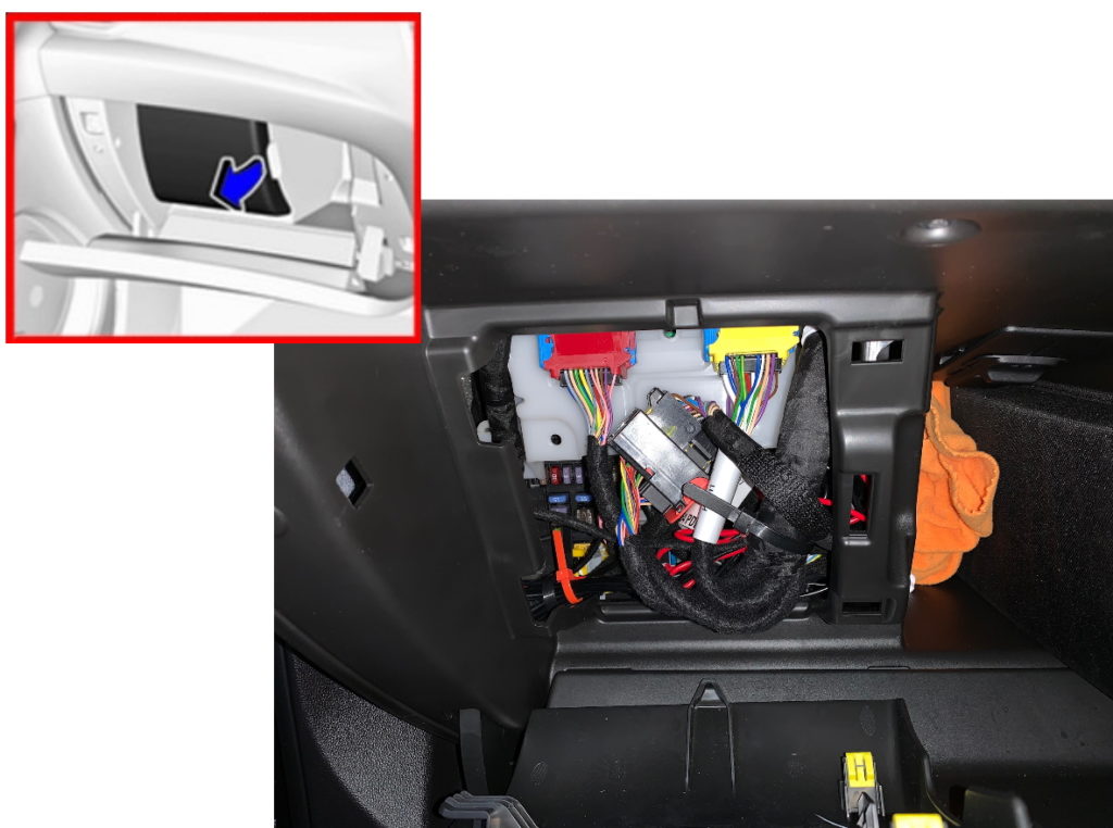
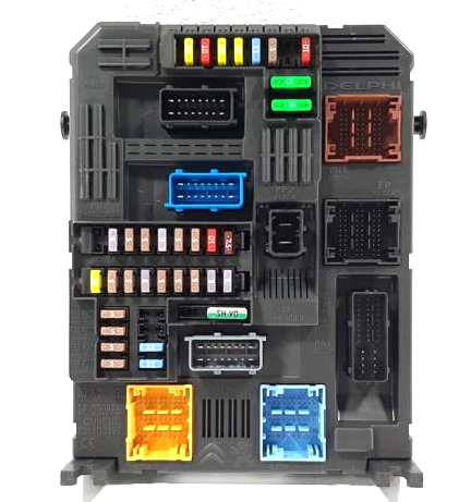
The fuse box itself will look something like this.
Diagram
Assignment
Type 1
| 1 | Interior mirror / Electric power steering wheel / Selective drive control / Radar / Diesel exhaust system |
| 3 | Trailer Position Control Module |
| 4 | Signal |
| 5 | Window washer (front/rear) |
| 6 | Window washer (front/rear) |
| 7 | Rear socket |
| 8 | Rear wiper |
| 10 | Door lock/rear door lock |
| 11 | Door lock/rear door lock |
| 12 | Stop-Start System / Diagnostic Connector Module / Brake System |
| 13 | Infotainment system / Climate control system |
| 14 | Alarm siren |
| 15 | Climate control system |
| 16 | Stop-start/Brake system |
| 17 | Instrument panel |
| 18 | Parking assistant |
| 19 | Steering Column Electrical System / Steering Wheel Controls |
| 21 | Anti-theft alarm |
| 22 | Camera / Rain sensor / Automatic lighting control |
| 23 | Seat belt reminder |
| 24 | Automatic Transmission /Advanced Parking Assist / Panoramic View System |
| 25 | Air bag |
| 26 | Electronic stability control |
| 27 | Anxiety |
| 28 | OnStar or BTA module |
| 29 | Infotainment system |
| 32 | Cigarette lighter/ front socket |
| 34 | Heated rear window / Heated windshield / Inductive charging |
| 35 | Light switch/ diagnostic connector module |
| 36 | Lighting |
In this version, fuse 32 is responsible for the operation of the cigarette lighter.
Type 2
| 1 | 3A Electronic Key System – Anti-Theft Alarm – Ignition Switch |
| 2 | 3A Steering angle sensor |
| 3 | 3A Instrument connector – comelec system |
| 4 | 7.5A Instrument connector – Diagnostic connector – Double brake pedal contactor – Central voltage maintainer |
| 5 | 5A Multi-function screen – Rear view camera – Parking assistance computer – Transmission control module |
| 6 | 15A Reserve |
| 7 | 10A Audio Amplifier |
| 8 | 20A Rear window wiper |
| 9 | 5A “Ground” of front and rear lamps |
| 10 | 30A Drive of central and internal locks of front and rear doors + fuel tank flap |
| 11 | 30A Power supply for drives of front and rear external and internal locks |
| 12 | 3A Security alarm |
| 13 | 3A Additional heater activation module |
| 14 | 15A |
| 15 | 5A |
| 16 | 5A Electric power steering |
| 17 | 10A 12B connector in trunk or cargo area |
| 18 | 5A Autonomous telematics unit – OnStar or BTA module |
| 19 | 5A |
| 20 | 15A Interior fuse box 3 |
| 21 | 3A Indoor lighting – Charger for portable lamp – Individual lamps |
| 22 | 3A Glove box lighting – Individual lamps |
| 23 | 3A Blind Spot Warning System – Exterior Mirror Adjustment – Inductive Charging |
| 24 | 5A Common Connection Unit – Steering Wheel Communication Module CV00 |
| 25 | 5A Switch for headlight range control – rear view mirror |
| 26 | 3A Instrument Connector – Driver and Passenger Seat Belt Display |
| 27 | 3A Rain and light sensor – Steering column switch |
| 28 | 10A Front center element – Multiplex front panel – Car radio – Display of information in the driver’s field of vision |
| 29 | 5A Motor switching unit (PSF1) |
| 30 | 15A Audio system |
| 31 | 5A Airbag control unit |
| 32 | 5A Reserve |
| 33 | 15A Cigarette lighter or instrument panel 12V connector |
| 34 | 3A Trailer connection box |
| 35 | 5A Instrument panel control computer |
| 36 | 20A Car radio |
| Relay | |
| R1 | Power + accessories |
| R2 | Power supply “plus” CAN “Comfort” |
| R3 | Rear window wiper |
| R4 – R9 | Electric motors for driving front and rear external and internal locks |
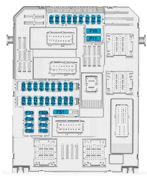
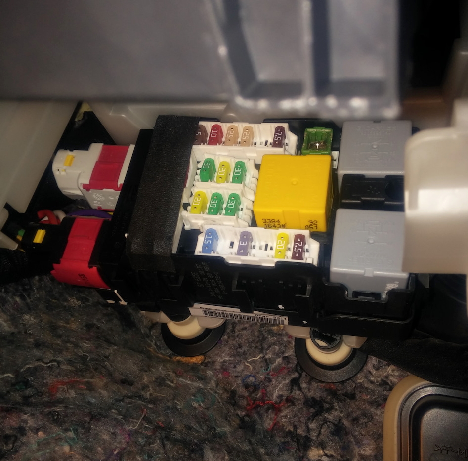
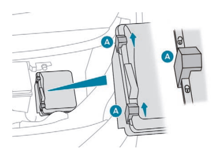
Fuse and relay box
This block is located behind the main fuse box and is mounted on the front wall of the passenger compartment.
Type 1
Photo example
Diagram
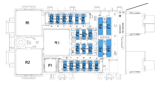
Designation
| F1 | 40A Heated rear window |
| F2 | 7.5A Electric mirrors |
| F3 | 20A Relay socket 230A ECO: Power front windows |
| F4 | 15A Trunk socket 12V |
| F5 | 30A Rear window lift motors |
| F6 | 30A Electric motors for front window lifters |
| F7 | 25A Heated seats |
| F8 | 20A Additional air fan for rear seats |
| F9 | 30A Power tailgate unit (6290) |
| F10 | 40A Left seat belt reel |
| F11 | 5/20A Trailer switching unit 7/13 channels |
| F12 | 30A Electrically adjustable driver’s seat |
| F13 | 30A Hatch 40A Right seat belt reel |
| F14 | 30A Power passenger seat |
| F15 | 30A Sunroof |
| F16 | 10A Rear view mirror unit |
| F17 | 10A Lighting and mirror memory unit |
| F18 | 25A Radio Amplifier |
| F19 | 30A Reserve |
| F20 | 3A Electric tailgate drive unit (6290) |
| F21 | 3A Trunk switch (6292) |
| F22 | 20A Reserve |
| F23 | 3A Trailer connection box |
| Relay | |
| R1 | 230A connector |
| R2 | Trunk socket 12V |
| R3 | Heated rear window and exterior mirrors |
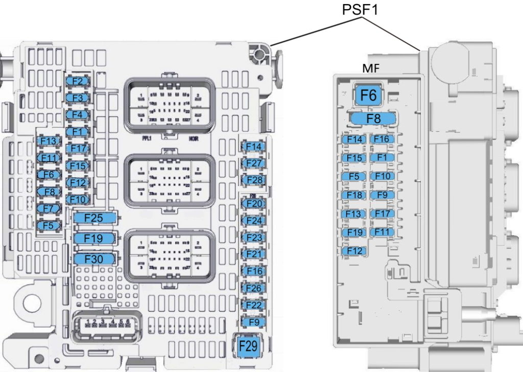
Type 2

Diagram

Allocation
| F1 | 40A Heater / rear window defroster |
| F2 | 10A Heated exterior side mirrors |
| F3 | 30A Electric windows – front |
| F4 | 10/15A Folding side mirrors / Adjustable outside mirrors |
| F5 | 30A Power windows – rear |
| F6 | Seat heating |
| F7 | – |
| F8 | Fuse Box (Right Side of Dashboard) |
| F9 | – |
| F10 | 20A Heated front seats |
| F11 | 20A Front seat massage function |
| F12 | Empty (reserved) |
| Relay | |
| R01 | Seat heating relay |
| R02 | Power window relay |
| R03 | Rear window defroster/heater relay |
| R04 | – |
| R05 | – |
| R06 | – |
| R07 | – |
Engine compartment
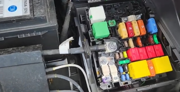
Fuse and relay box
In the engine compartment, under the hood, on the left side, next to the battery, there is a fuse and relay box. An example of access is shown in the layout.
Layout
Type 1
Photo example

Diagram
Appointment
| 1 | 15A Engine control, Pressure conversion relay activation (1032) – Diesel injectors |
| 2 | 5A Electric fan relay control |
| 3 | 5A Starter/Alternator K207 Battery Control Module |
| 4 | 5A SCR injector, P17 Information display module |
| 5 | 15A Diesel fuel booster pump, Fuel pump |
| 6 | 20A Engine control, controlled fuel pump |
| 7 | 10A Solenoid valve for diesel fuel supply control pump – Proportional solenoid valve TGV |
| 8 | 10A Water in diesel fuel sensor – Oil pump electra valve – NOx sensor DW10F |
| 9 | 10A Electric ignition switch P16 Instrument panel |
| 10 | 5A Start/Stop relay KL9 |
| 11 | 15A Switching and protection unit control – Fuel additive pump – Traction control switch |
| 12 | 5A Reserve |
| 13 | 5A Network voltage maintenance device |
| 14 | 25A A/C compressor solenoid |
| 15 | 5A Power Steering Computer, Diagnostic Connector, Vehicle Distance Assist (Radar) |
| 16 | 20A Rear air conditioning unit pump |
| 17 | 10A Intelligent Switching Box |
| 18 | |
| 19 | 30A Reserve |
| 20 | 15A Power supply for front and rear windshield washer pumps |
| 21 | 20A Headlight washer pump |
| 22 | 15A Horn |
| 23 | 15A Right headlights |
| 24 | 15A Left headlights |
| 25 | 30A Reserve |
| 26 | |
| 27 | 5A Reserve |
| 28 | 5A |
| 29 | 30A Starter |
| 30 | 30A Diesel fuel heater |
| MF1 | 5A With controlled air intake module |
| MF11 | 5A Reserve |
| MF12 | 15A Automatic transmission computer AX6 |
| MF13 | 20A Heater (coolant and interior heating) |
| MF14 | Comelec automatic transmission |
| MF15 | Reserve |
| MF16 | Reserve |
| MF17 | Reserve |
| MF18 | 5A Double Brake Pedal Contactor |
| MF19 | 5A Reserve |
| Relay | |
| R1 | Diesel engine control computer |
| R2 | Switching off the engine communication unit |
| R3 | Switching off the engine communication unit |
| R4 | Engine computer, central voltage maintainer, electric fan, reversing generator |
| R5 | Fuel Pump – NOX Sensor |
| R6 | Electrical power from the ignition switch |
| R7 | Starter |
Type 2
Photo
Diagram
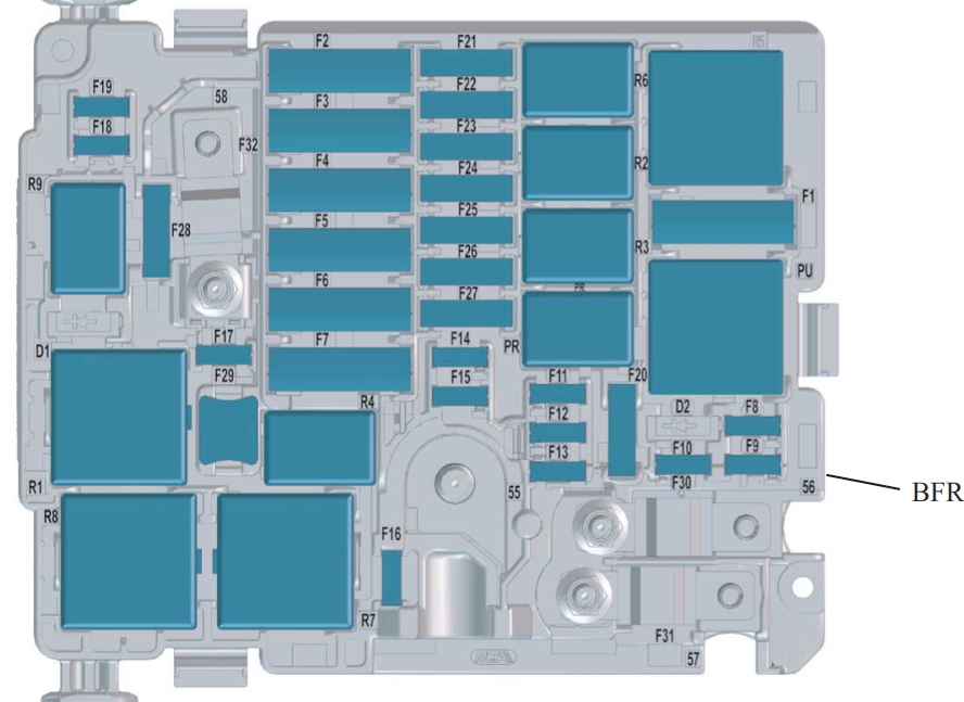
Decoding
| F1 | 40A Air conditioner fan |
| F2 | 60A Computer ABS/ESP system |
| F3 | 80A Interior fuse box 3 |
| F4 | 30A computer ABS/ESP system |
| F5 | 50A Intelligent Switch Unit (Right turn signals, front right side marker lights, right brake lights, left reverse lights, right fog lights.) 20A Heated windshield |
| F6 | 60A Two-speed cooling fan control unit (GMV) 20A BVA AxN8 calculator – BVA Ax6III calculator (thermal) |
| F7 | 70A Intelligent Switching Box |
| F8 | 15A Engine Control Fuel Pump, Pilot Controlled Thermostat – Oil Pump Solenoid Valve (EC Flush – Electrical Solenoid Valve – Intake Air Flow Meter – Oxygen Sensors (EP6FADTX), Pilot Controlled Thermostat – Switchable Water Supply, Electrical Solenoid Valve (EP6FDT) 20A Computer engine (for EB2DT or EP6FDT) l Controlled booster pump (for DV6F or DW10F) |
| F9 | 15A Piloted lift pump (DW10F), intake and exhaust valves v solenoid valves – Piloted thermostat – Oil pump solenoid valve (EC flush – Electrical solenoid valve – Intake air flow meter – Oxygen sensors (EP6FADTX), Piloted thermostat – Switchable Water Supply Electric Solenoid Valve (EP6FDT) |
| F10 | 15A Engine Computer – Diesel Flow Control Pump Solenoid – Turbocharger Pressure Control Solenoid Valve (DV5R and DW10F) – Thermostat S (DV5R) – Purge Heater – Adjustable Intake and Exhaust Valve Solenoid Valves (EP6FADTX) – Cylinder Flush – Oxygen Sensors Raised (EB2ADTS ) ) |
| F11 | 20A Engine computer |
| F12 | 5A Instruments – GMV relay – Istars – DMTC, electric water cooling with turbocharging (EB2ADTS and EP6FADTX), intelligent service unit (EP6FADTX) |
| F13 | 5A Intelligent Switch Box |
| F14 | 5A Battery charge level block |
| F15 | 20A Electrically heated windshield |
| F16 | 15A Fog lights 10A Daytime running lights |
| F17 | 10A GMP relay diagnostics BFRM – BSI1 – Engine computer – Lower Nox sensor (injectors DV5R and DW10 (DV5R) |
| F18 | 10A Right headlights high beam |
| F19 | 10A Left headlights high beam |
| F20 | 30A Engine computer l Charge pump (for ER6EDT) – ignition coils (EB2ADTS and EP6FADTX) |
| F21 | 30A Starter |
| F22 | 40A Reserve – Taxi |
| F23 | 40A Starter/Alternator |
| F24 | 40A Fuse box in passenger compartment 5 |
| F25 | 40A Interior fuse box 3 |
| F26 | 15/20A Heater |
| F27 | 25A Intelligent Switching Unit (Right Low Beam Headlight – Right Reversing Lights – Left Fog Lights – Left Rear Parking Lights – Third Brake Light.) |
| F28 | 30A Power supply for urea pump and urea tube heating resistor (UCE or DV5R) – Nox sensor (DW10F) – Engine computer (EP6FADTX) – (BlueInjection, AdBlue) |
| F29 | 40A Windshield wiper |
| F30 | 80A Pre-heating unit |
| F31 | 80A Switching and protection unit |
| F32 | 80A Power steering, Left low beam headlight – Static turn lights – Side turn indicators – Left turn indicators – Front left and rear right side lights – Left brake lights – License plate lights. |
| Relay | |
| R1 | Engine control computer / Euro6 diesel (SCR module power supply) |
| R2 | Air Conditioning Compressor/Heated Windshield |
| R3 | Starter / thermal preconditioning |
| R4 | Fog lights/daytime running lights |
| R5 | Air conditioner fan |
| R6 | Starter |
| R7 | Front wiper |
| R8 | Front wiper |
| R9 | Headlights |
Battery fuse box
A high power fuse box is attached to the positive terminal of the battery.
Diagram
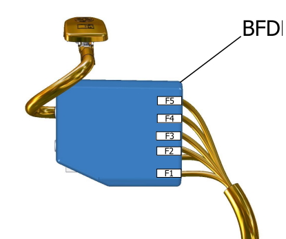
Appointment
- 60A – Electrical control unit for two-speed fan motor
- 100A – Fuse box
- 80A – Power steering
- 80A – Interior fuse box
- 80A – Interior fuse box
If you find a mistake or have something to add, write in the comments.
Hi could any please tell me what is in position D2 in a type 2 fuse box for a 2021 Peugeot 3008 plug in hybrid. Many thanks. PHILIP. Hazell
D2 : est une minidiode lié avec la cavity 17 (voir le fils derrière la box) ce fils est la commande relais principal contrôle moteur.
Which is the principal relay from the psf1 fusebox
Hallo i have a 3008 suv diesel year 2020 and i can not locate fuse for left front head light. can somebody please assist_
Hello ..