The family sedan Peugeot 408 was presented at the international auto show back in 2010. This car was also produced in 2011, 2012, 2013, 2014, 2015, 2016, 2017, 2018. We provide an assignment of the Peugeot 408 fuse boxes with their diagrams, as well as note the fuse responsible for the cigarette lighter.

Engine compartment
There are two fuse boxes in the engine compartment.

Main box
In the figure it is designated under the number 1 and is closed with a protective cover.

Diagram

Assignment
- F1 – 20A Power supply to the engine ECU.
- F2 – 15A Sound signal.
- F3 – 10A Windscreen washer.
- F4 – 20A Headlight washer.
- F5 – 15A Canister unloading solenoid valves, fuel pump.
- F6 – 10A Vehicle speed sensor circuit, ABS / ESC system, automatic transmission processor.
- F7 – 10A Power steering processor, brake.
- F8 – 25A Starter switch.
- F9 – 10A Coolant level sensor, manual headlight control.
- F10 – 30A Components of the electronic engine management system (on gasoline: ignition coils, solenoid valves, oxygen sensors, injectors, heating system elements, fuel pump, electronic thermostat).
- F11 – 40A Air conditioning fan.
- F12 – 30A Low / high speed of the windshield wiper.
- F13 – 40A Power supply to the intelligent switching unit (ignition switch).
- F15 – 10A Right high beam headlamp.
- F16 – 10A Left high beam headlamp.
- F17 – 15A Left low beam headlamp.
- F18 – 15A Right-hand dipped beam headlamp.
- F19 – 15A Ignition coil.
- F21 – 5A Power supply for the engine cooling fan relay.
Fuses on the battery cover
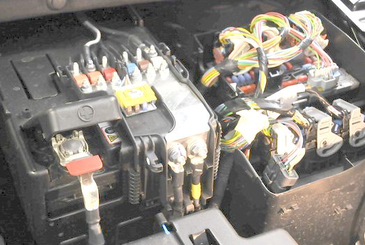
The fuse and fuse box is located on the battery terminal.

Purpose: type 1
| 1 | 30A Electric motor of the Valvetronic system (1.6 l THP 16V) |
| 2 | 30A Electro pump for sequential gearbox |
| 3 | 50A Reserve |
| 4 | 100A Switch unit and protection system |
| 5 | 70A ECU heating system (diesel engine) |
| 6 | 80A Electric power steering pump |
| 7 | 15A Transmission (sequential or automatic) |
| 8 | 15A Diagnostic connector, daytime running lights |
| 9 | 5A Two functional brake contactor |
| 10 | Reserve |
Depending on the configuration, the region of sale and the year of manufacture, its different design is possible.

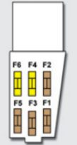
Purpose: type 2
F1 15 A Automatic transmission.
F2 15 A Diagnostic connector.
F3 5 A Brake light contact.
F4 5 A Heated jets.
Passenger compartment
The unit is located on the left side under the dashboard.

Location

Diagram

Designation
- F2 30 A Locking / unlocking system.
- F3 5 A Airbag / tensioner processor, exterior mirrors.
- F4 10 A Contactor for clutch pedal and dual function brake contactor, air conditioning, steering wheel position sensor, automatic transmission, ESC system.
- F5 30 A Front impulse windows.
- F6 30 A Rear impulse windows.
- F7 5 A Front and rear lamps, individual lamps, rear spot lamps, sun visor mirror illumination, glove box illumination.
- F8 20 A Car radio, multifunction display, pre-installed system for aftermarket burglar alarm.
- F9 30 A 12V socket, front, pre-installed system for aftermarket installation of car radio.
- F10 15 A Automatic transmission, STOP contactor.
- F11 15 A Circuit of a weak current of the ignition switch.
- F13 5 A Electronic engine management system.
- F14 15 A Instrument panel, airbags, climate control, multifunction display.
- F15 30 A Locking / unlocking system.
- F17 40 A Heated rear window and exterior mirrors.
The fuse number 9, 30A, is responsible for the cigarette lighter.
Anything to add? We will be glad to receive your comments.
 FuseAndRelay.com