Nissan Terrano belongs to the SUV class. 1st and 2nd generations have been produced since 1986. Years of release of 3rd generation: 2013, 2014, 2015, 2016, 2017, 2018, 2019, 2020, 2021. We will show pictures of fuse boxes and relays for all three generations of Nissan Terrano, their diagrams with the designation of the elements. And also select the fuse responsible for the cigarette lighter.
Attention, the number of elements in the boxes depends on the degree of electrical equipment of your car, the year of manufacture and the country of delivery. Check the exact description with the designation on the back of the cover.
Contents
1st and 2nd generation
This section presents the most popular fuse and relay boxes for vehicles manufactured before 2013.
Passenger compartment
Located in the dashboard behind the protective cover near the steering rack.

Type 1
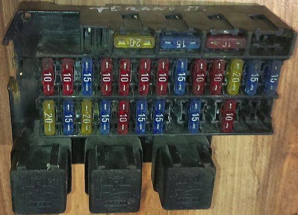
The photo

Type 2

Type 3
The photo
Если можете помочь дополнить расшифровку – пишите в комментарии.
Engine compartment
It will be located near the battery. The exact designation will be applied but its cover.

Photo for example
Diagram

Relay
The relay elements are located both in the passenger compartment and in the engine compartment. Here’s one of the options.

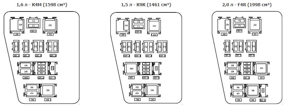
3rd generation
Type 1
Engine compartment
Located on the left side, under the protective cover.
Diagram

Assignment
| F1 | Not used |
| F2 | Not used |
| F3 (25) | Chains: fuel pump and ignition coils; main relay K5 engine management system |
| F4 (15) | A / C Compressor Electromagnetic Clutch Circuit |
| F5 (40) | Power circuits: low speed relay of the cooling fan |
| F6 (60) | Chains protected by fuses F9, F10, F28, F29, F30, F31, F32, F36 of the mounting block 1 in the passenger compartment |
| F7 (60) | Chains protected by fuses F13, F14, F15, F16, F17, F18, F19, F20, F24, F26, F27, F37, F38, F39 of the mounting block in the passenger compartment |
| F8 (60) | Chains protected by fuses F1, F2, F3, F4, F5, F11, F12 of the mounting block in the passenger compartment |
| F9 (25) | Live circuits in position S and A of the ignition key |
| F10 (80) | Power circuits of the relay for turning on the electric heater of the passenger compartment |
| F11 (50) and F12 (25) | ABS Control Unit Chains |
Relay designation
- K1 – Relay high speed cooling fan
- K2 – Air conditioner relay
- KZ – Relay of low speed of the fan of the cooling system
- K4 – Relay of the fuel pump and ignition coils
- K5 – The main relay of the engine management system
- K6 – Not used
- K7 – Fog lamp relay. If it is not, then the PTF is not installed.
- K8 – Heater fan relay
Other versions of this box
Passenger compartment
Located at the end of the dashboard, which is closed by the driver’s door, behind the cover.
Diagram

Protected components
| F1 (20) | Chains: windshield wiper; winding relay for heating the glass of the tailgate |
| F2 (5) | Chains: power supply of the instrument cluster; windings of the K4 relay of the fuel pump and ignition coils; at the power supply of the ECU of the engine control system from the ignition switch; |
| F3 (10) | Brake light circuits |
| F4 (10) | Chains: turn signal lamps; diagnostic connector of the engine management system (pin 1); immobilizer coils; switching unit |
| F5 (5) | Rear gear electromagnetic clutch control circuit |
| F6 | Reserve |
| F7 | Reserve |
| F8 | Reserve |
| F9 (10) | Circuit of a low beam lamp of the left headlight unit |
| F10 (10) | Circuit of a low beam lamp of the right headlight unit |
| F11 (10) | Chains: lamps of a high beam of the left headlight unit; headlight high beam indicator in the instrument cluster |
| F12 (10) | Circuit of a lamp of a high beam of the right block of headlights |
| F13 (30) | Rear door power window chains |
| F14 (30) | Chains of the electric windows of the front doors |
| F15 (10) | ABS control unit circuit |
| F16 (15) | Driver and front passenger seat heating circuits |
| F17 (15) | Beep circuits |
| F18 (10) | Chains: side light bulbs of the left headlamp; side light bulbs left rear light |
| F19 (10) | Chains: side light bulbs of the right headlamp; side light lamps for the right rear light; license plate lighting lamps; glove box lamps; illumination of the instrument cluster and controls on the instrument panel, console and floor tunnel lining |
| F20 (7.5) | Rear Fog Lamp Circuit |
| F21 (5) | Chains of heating elements of external rear-view mirrors |
| F22 | Reserve |
| F23 | Reserve |
| F24 (5) | Power steering control circuit |
| F26 (5) | Airbag Control Unit Circuit |
| F27 (20) | Chains: parking sensors; reversing light bulbs; windshield washer and tailgate glass |
| F28 (15) | Chains: lamps of the interior lighting plafond; luggage compartment lamp; head unit illumination lamps |
| F29 (15) | Chains: intermittent operation of the windshield wiper; turn signal switch; alarm switch; central lock control; buzzer; diagnostic connector of the engine management system |
| F30 (20) | Central locking chains |
| F31 (15) | Fog lamp chain |
| F32 (30) | Power circuit of the relay of heated glass of a luggage compartment door |
| F33 | Reserve |
| F34 (15) | Rear gear electromagnetic clutch circuit |
| F35 | Reserve |
| F36 (30) | Power circuit of relay K8 heater fan |
| F37 (5) | Chains of electric drives of external rear-view mirrors |
| F38 (15) | Renault duster cigarette lighter; power supply of the head unit of sound reproduction from the ignition switch |
| F39 (10) | Heating, air conditioning and ventilation motor relay |
The fuse number 38 is responsible for the cigarette lighter.
Separately, under the anti-theft device, along the dashboard beam, there can be a relay for an additional heater of the passenger compartment (1067 – 1068), and under the instrument panel, a relay for heating the rear window (235).
Type 2
Engine compartment
Located next to the battery, covered with a protective cover.
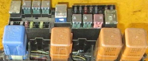
The photo

Diagram

Designation
| Ef1 | 10A Fog lights |
| Ef2 | 7.5A Electrical control unit |
| Ef3 | 30A Heated rear window, heaters outside mirrors |
| Ef4 | 25A Stability control unit |
| Ef5 | 60A Fuse chains P11, P24-P27, P34, P39, P41 |
| Ef6 | 60A Ignition switch (lock), P28 fuse circuits. P31, P38, P43, P46, P47 |
| Ef7 | 50A Stability control unit |
| Ef8 | 80A Luggage compartment socket |
| Ef9 | 20A Reserve |
| Ef10 | 40A Heated windshield 1 |
| Ef11 | 40A Heated windscreen 2 |
| Ef12 | 30A Starter |
| Ef13 | 15A Reserve |
| Ef14 | 25A Electronic engine management system |
| Ef15 | 15A A / C compressor clutch relay, A / C compressor clutch |
| Ef16 | 50A Electro cooling fan |
| Ef17 | 40A Automatic gearbox control unit |
| Ef18 | 80A Electric power steering pump |
| Ef19 | Reserve |
| Ef20 | Reserve |
| Ef21 | 15A Oxygen concentration sensors, canister purge valve, camshaft position sensor, phase change valve |
| Ef22 | Electronic engine control unit (ECU), electric cooling fan control unit, ignition coils, fuel injectors, fuel pump |
| Ef23 | Fuel pump |
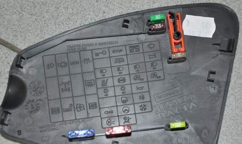
Passenger compartment
Located on the side of the dashboard, behind the driver’s side cover.
the photo

Diagram
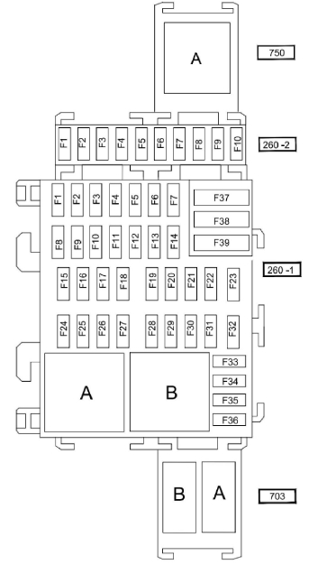
Pinout of fuses for 260-2
- Reserve
- 25A – Electrical equipment control unit, left headlight block, right headlight block
- 5A – All-wheel drive transmission (4WD)
- Reserve / 15A Additional control unit for electrical equipment
- 15A Connector for connecting additional equipment at the back ( socket )
- 5A – Electrical equipment control unit
- Reserve
- 7.5A – No data
- Reserve
- Reserve
- Relay A – Rear power window lock
Pinout for 260-1 (main board)
- 30A – Power window front door
- 10A – High beam of the left headlight
- 10A – High beam of the right headlight
- 10A – Low beam of the left headlight
- 10A – Low beam of the right headlight
- 5A – Rear lights
- 5A – Front parking lights
- 30A – Power window rear door
- 7,5A – Rear fog lamp
- 15A – Sound signal
- 20A – Automatic door lock
- 5A – ABS systems – ESC, brake light switch
- 10A – Plafond lighting, luggage compartment lighting, glove compartment lighting
- Not used
- 15A – Windshield wiper
- 15A – Multimedia system
- 7,5A – Fluorescent lamps
- 7.5A – Stop light
- 5A – Injection system, instrument panel, central electronic switching unit in the cabin
- 5A – Airbag
- 7.5A – All-wheel drive transmission with 4 driving wheels (4WD), reverse gear
- 5A – Power steering
- 5A – Speed controller / limiter, rear window relay, seat belt not fastened signal, parking distance control system, relay for additional heating of the passenger compartment
- 15A – UCH (passenger compartment central electronic switching unit)
- 5A – UCH (passenger compartment central electronic switching unit)
- 15A – Direction indicators
- 20A – Steering column switches
- 15A – Sound signal
- 25A – Steering column switches
- Not used
- 5A – Instrument panel
- 7,5А – Radio receiver, control panel for cabin air conditioning, interior ventilation, rear connector for connecting electrical accessories
- 20A – Cigarette lighter
- 15A – Diagnostic connector and connector for audio system
- 5A – Heated rearview mirror
- 5A – Exterior mirrors with electric drive
- 30A – Central electronic switching unit of the passenger compartment, starter
- 30A – Windshield wiper
- 40A – Ventilation of the passenger compartment
- Relay A – Electro air conditioner fan
- Relay B – Heated mirrors
The fuse number 33 is responsible for the cigarette lighter.
Relay 703: B – Reserve, A – Additional socket in the luggage compartment
We have posted a video on our YouTube channel. Watch and subscribe.
And if there is anything to add, we will be glad to receive your comments.