Nissan Sylphy B18 represents the eighth generation of the Sylphy model range, which was produced in 2020, 2021, 2022, 2023, 2024, 2025, 2026. During this time, the model received a facelift. In this publication you will be able to find a description of the fuses and relays of the Nissan Sylphy B18 with fuse box diagrams, their locations and photo examples of execution. Also highlight the cigarette lighter fuse.
Purpose of fuses and relays may differ from that described here and depends on the year of manufacture and the level of electrical equipment in your vehicle.
Passenger compartment
In the passenger compartment, the fuse box with fuses and relays is located at the bottom of the dashboard behind the glove compartment.
Photo for example

Check the actual description with yours on the back side of the protective cover.

Diagram

Assignment
| 1 | VDC CONT – Vehicle Dynamic Control module (stability/traction control system) |
| 2 | ADAS – Advanced Driver Assistance Systems (radar, sensors, lane assist, etc.) |
| 3 | STOP LAMP-1 – Brake light circuit (main stop lamps) |
| 5 | CLUTCH – Clutch switch (manual transmission interlock, engine start circuit) |
| 6 | ELEC PARTS (AUTO ACC) – Electrical parts powered in AUTO ACC mode (accessories) |
| 7 | POWER WDW FR LH – Power window, front left (driver side) |
| 11 | SUNROOF – Sunroof motor and control switch |
| 13 | USB – USB charging ports / infotainment USB input |
| 17 | CONSULT – Diagnostic communication (Nissan CONSULT tool interface) |
| 18 | CAN GATEWAY – Controller Area Network Gateway (communication between modules) |
| 19 | FOG LAMP RR – Rear fog lamp |
| 20 | HEATED SEAT FR RH – Heated seat, front passenger |
| 21 | HEATED SEAT FR LH – Heated seat, front driver |
| 23 | POWER SEAT – Electric seat adjustment (driver/passenger depending on trim) |
| 24 | SPARE – Not used |
| 26 | DOOR LOCK FR – Door lock actuator, front right |
| 27 | DOOR LOCK RR – Door lock actuator, rear right |
| 28 | HAZARD LAMP – Hazard warning lights (emergency flashers) |
| 29 | HFM – Hands-Free Module (Bluetooth, phone system) |
| 30 | BCM SIGNAL – Body Control Module signal circuits |
| 31 | SPARE – Not used |
| 32 | STOP LAMP 2 – Secondary brake light circuit (includes high-mounted stop lamp) |
| 33 | TCU – Transmission Control Unit (CVT control) |
| 34 | ROOM LAMP – Interior dome light / courtesy lamps |
| 35 | SPARE – Not used |
| 36 | AUDIO AMP – Audio system amplifier |
| 37 | SPARE – Not used |
| 38 | AUDIO – Audio system head unit |
| 39 | BCM SIGNAL – Body Control Module signal circuits (secondary) |
| 40 | METER (BAT) – Instrument cluster (battery supply) |
| 41 | POWER SOCKET – 12V accessory power outlet (cigarette lighter socket) |
| 42 | HEATED STRG – Heated steering wheel |
| 43 | WASH PUMP – Windshield washer pump |
| 44 | BLOWER – HVAC blower motor |
| 45 | SPARE – Not used |
| 46 | RR DEF – Rear defogger (rear window heater) |
| 48 | AIR BAG – Supplemental Restraint System (SRS airbag control unit) |
| 49 | METER (IG1) – Instrument cluster (ignition supply) |
| 50 | ELEC PARTS (IGN) – General electrical parts powered with ignition ON |
| 51 | ELEC PARTS (IGN-RUN) – Electrical parts powered when ignition is in RUN position |
| 52 | STRG SENSOR – Steering angle sensor (VDC/ADAS input) |
| 53 | HEATED MIRROR – Heated exterior mirrors |
| 56 | POWER WDW FR RH – Power window, front right (passenger side) |
| 57 | POWER WDW RR – Power window, rear right |
| R1 | AUTO ACC RELAY: Supplies accessory circuits in AUTO mode |
| R2 | POWER WDW RELAY: Power windows relay |
| R3 | IGN 2 RELAY: Secondary ignition relay |
| R5 | RR DEF RELAY: Rear defogger relay |
| R6 | ROOM LAMP RELAY: Interior room/courtesy light relay |
| R7 | IGN RELAY: Main ignition relay |
Fuse number 41 is responsible for the cigarette lighter.
Engine compartment
Under the hood in the engine compartment there are 3 blocks with fuses

Fuse box 1

Diagram

Designation
| F1 | – |
| F2 | 20A BAT, ABS Valves (Brake Anti-lock System valves) |
| F3 | 20A Fuel Pump |
| F4 | 15A Actuator 1 |
| F5 | 15A Actuator 3 |
| F6 | 15A Actuator 2 |
| F7 | 15A Actuator 4 |
| F8 | 15A Actuator 5 |
| F9 | 30A Wiper (front wiper motor) |
| F10 | 30A LCS Cabin Injector (likely Low Current System / injector control) |
| F11 | 15A ATL / LPG (Alt/LPG system, alternate fuel if equipped) |
| F12 | 10A Airbag / ABS (Supplemental Restraint + Anti-lock system) |
| F13 | 7,5A Reverse Lamp / A/C Valve (back-up lights, A/C solenoid valve) |
| F14 | – |
| F15 | 5A ECM (Engine Control Module) |
The “Actuator” fuses (F4–F8) usually feed throttle control motor, purge solenoid, valve timing solenoids, etc. (depends on engine variant).
- F2 (ABS valves) and F12 (Airbag/ABS) are critical safety circuits.
F13 often powers both the reverse light and A/C control solenoid.
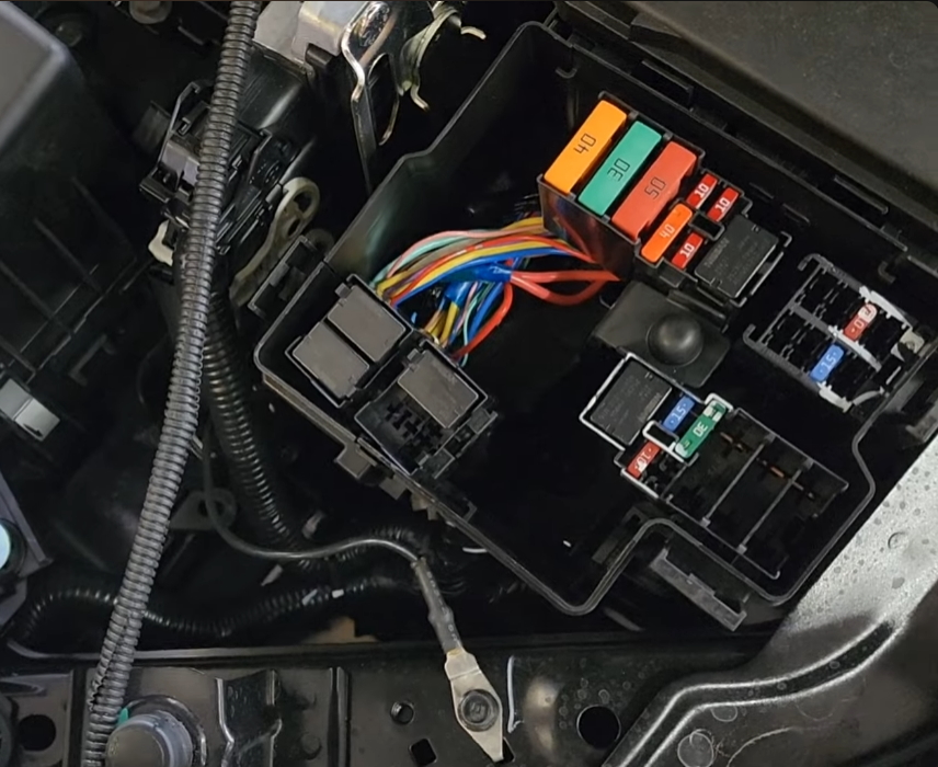
Fuse box 2
Photo
Fuse Box Cover Diagram
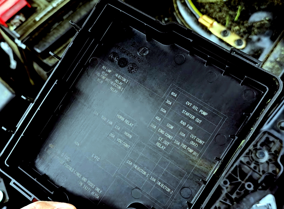
Allocation
| CVT Oil Pump | 60A Powers the oil pump for CVT lubrication and cooling. |
| Starter Cut | 30A Controls starter motor cut-off to prevent operation in certain conditions. |
| Radiator Fan (Rad Fan) | 50A Powers the radiator fan for engine cooling. |
| USM | 40A Controls electronic modules under the seat or other system modules. |
| Radiator Fan (Rad Fan) | 10A Additional fuse for radiator fan, possibly low-speed operation. |
| CVT Control (Battery) | 10A Powers the CVT control unit. |
| Engine Control (Eng Cont) | 10A Powers the engine control unit or related circuits. |
| Fuel Pump (INJ) | 10A Powers the fuel pump for fuel injection. |
| Starter Cut Relay (ST Cut Relay) | 10A Controls cutting off the starter motor. |
| Injector 1 | 15A Powers fuel injector circuit 1. |
| Injector 2 | 10A Powers fuel injector circuit 2. |
| Horn | 15A Powers the horn for signaling. |
| Radiator Fan (Rad Fan) | 10A Additional fuse for radiator fan. |
| Vehicle Dynamic Control (VDC Cont) | 30A Powers the vehicle dynamic control system for stability and traction. |
| Injector 1 Relay | Controls power to fuel injector 1. |
| Injector 2 Relay | Controls power to fuel injector 2. |
| Horn Relay | Controls power to the horn circuit. |
Fuse box 3
On the positive terminal of the battery, under the red protective cover, there is a block of high-power power fuses.

On our YouTube channel, we also posted a video. Watch and subscribe.
If you know how to make the post better, write in the comments.