The Nissan Sylphy B17 represents the third generation of the Sylphy model line, which was produced in 2012, 2013, 2014, 2015, 2017, 2018, and 2019. In this article, you’ll find a description of the Nissan Sylphy B17 fuses and relays, complete with fuse box diagrams, their locations and photo examples. We’ll highlight the fuse responsible for the cigarette lighter.

The purpose of fuses and relays may differ from that described here and depends on the year of manufacture and the level of electrical equipment in your vehicle.
Contents
Passenger compartment
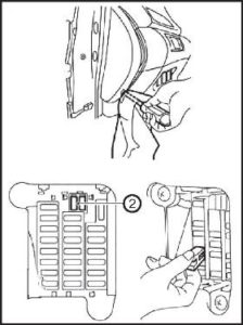
Fuse box located in the dashboard, on the rear left.
The photo
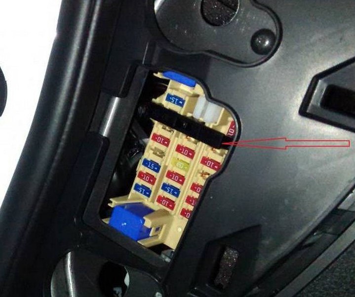
Attention, check the assignment with your diagram on the back of the protective cover.
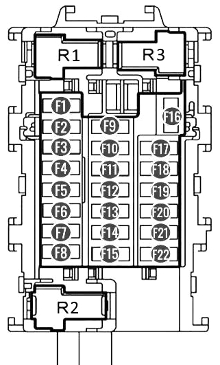
Diagram
Assignment
| F1 | 15A Cigarette Lighter |
| F2 | Not involved |
| F3 | 10A Audio system, power rear-view mirror No. 1 |
| F4 | 10A Audio system, power rear-view mirror No. 2 |
| F5 | 10A IPDM IG2 – fuse box in the engine compartment |
| F6 | 15A BLOWER MOTOR – Interior heating, heating motor |
| F7 | 10A A/C – Air conditioning |
| F8 | 15A BLOWER MOTOR – Interior heating, heating motor |
| F9 | 10A ELEC – Additional electrical equipment |
| F10 | Not involved |
| F11 | 10A METER – instrument cluster |
| F12 | 20A TRAILER – trailer electrical equipment |
| F13 | 15A ROOM LAMP – interior lighting and ceiling lamps |
| F14 | 10A HEATED SEATS – heated seats |
| F15 | 15A Push Eng Start – keyless engine start system |
| F16 | 10A HEATED MIRORR – heating / heating of rear-view mirrors |
| F17 | Not involved |
| F18 | 10A METER – instrument cluster |
| F19 | 10A ELEC – Additional electrical equipment |
| F20 | 10A WASHER – Windshield washer |
| F21 | 10A AIR BAG – Airbag |
Fuse number F1 is responsible for the cigarette lighter. An example of its replacement is in our video.

Relay
- Relay additional equipment of salon
- Blower fan relay
- –
Here is a video example of accessing the unit and replacing the fuse.
Engine compartment
Layout

Fuse and relay box
In the diagrams, it is designated as number 2. Located at the very edge of the motor space. To access it is necessary to remove the air filter sleeve.

Diagram from fuse box

Diagram

Designation
| F1 | 20A Heated rear door glass, heated rear-view mirrors |
| F2 | Not used |
| F3 | 20A Engine management system |
| F4 | Not used |
| F5 | 30A Windshield wiper, wipers |
| F6 | 10A Right dimensions |
| F7 | 10A Left dimensions |
| F8 | Not used |
| F9 | 10A A / C compressor clutch |
| F10 | 15A Fog lights |
| F11 | 10A High beam lamps, right headlights |
| F12 | 10A High beam lamps, left headlights |
| F13 | 15A Low beam lamps, left headlights |
| F14 | 15A Low beam lamps, right headlights |
| F15 | 10A Engine management system |
| F16 | 10A Reversing lamp |
| F17 | 10A Anti-lock braking system |
| F18 | Not used |
| F19 | Not used |
| F20 | 15A Fuel pump |
| F21 | 15A Ignition system |
| F22 | 15A injection system |
| F23 | Not used |
| F24 | 15A ETC – Accessories, Power steering |
Relay designation
- R8 Rear door heater relay
- R17 Relay for lowering (-) revolutions of the cooling fan
- R18 Relay for increasing (+) revolutions of the cooling fan
- R20 Ignition system relay
Fuse box
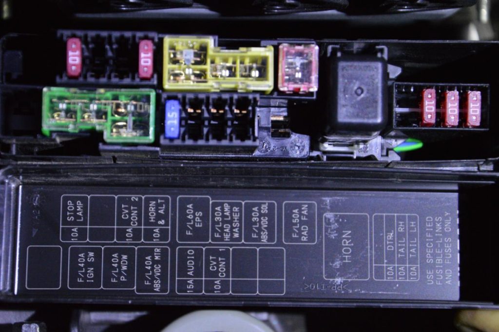
Indicated by number 3. To gain access to the fuses of the box on the casing of the electronic engine control unit, squeeze the cover latch. On the inner side of which, the current layout of the elements will be applied.
Diagram
Allocation
| R1 | Horn relay |
| 1 | 10A Stop lamps |
| 2 | 10A DTRL- Throttle assembly |
| 3 | 10A CVT CONT 2 – Transmission control module |
| 4 | 10A HORN & ALT – Horn and generator |
| 5 | 60A EPS – power steering |
| 6 | 30A HEAD LAMP WASHER – headlight washer |
| 7 | 30A ABS/YDC Sol – ABS brake system |
| 8 | 50/40A RAD FAN – Engine cooling radiator fan |
| 9 | Not involved |
| 10 | 40A IGN SW – Ignition system |
| 11 | 40A WDW – Power windows |
| 12 | 40A ABS / VDC MTR – ABS braking system, body electrical equipment |
| 13 | 15A Audio system (radio) |
| 14 | 10A CVT CONT 1 – Transmission control module |
| 15 | 15A Bose audio system (select models) |
| 16 | 15A Bose audio system (select models) |
| 17 | Not involved |
| 18 | 10A DTRL – Throttle assembly |
| 19 | 10A TAIL RH – Tail light bulbs on the right side |
| 20 | 10A TAIL LH – Taillight lamps on the left side |
Power fuse box
It is located on the positive terminal of the battery and is a group of fusible links that protect the fuse boxes in the passenger compartment and under the hood. On the diagrams it is marked with number 4. In case of complete absence of voltage, we recommend starting the test with them.

On our YouTube channel, we also posted a video. Watch and subscribe.
Is there anything to add to the post? We will be glad to receive your comments.