The second – generation Nissan Rogue was produced in 2014, 2015, 2016, 2017, 2018, 2019, 2020 with the model code T32. During this time, the model was updated. In this article, you can find describing the fuses and relays in the Nissan Rogue 2G, including fuse box diagrams, their locations, and photo examples. We’ll highlight the cigarette lighter fuse.

The purpose of fuses and relays may differ from that described here and depends on the year of manufacture and the level of electrical equipment in your vehicle.
Contents
Passenger compartment
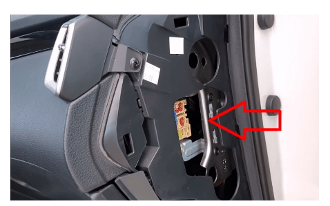
They are located at the end of the instrument panel on both sides.
Left box (main)
The protective cover must be removed for access.

Photo for example

Check the actual description with yours on the back side of the protective cover.

Diagram
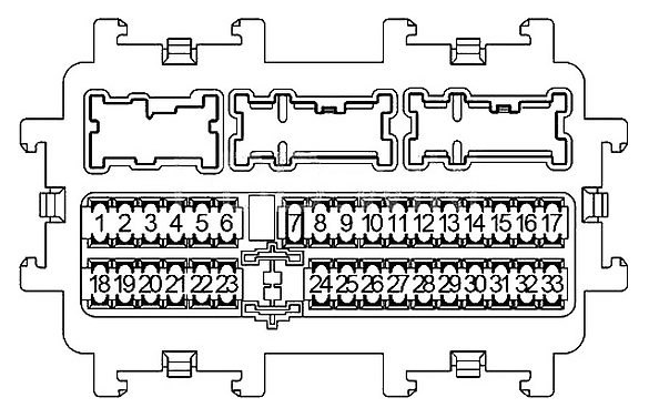
Assignment
| 1 | 15A Combination Switch, Pump Control Unit, Washer Switching Solenoid Valve |
| 2 | 10A Air Bag Diagnosis Sensor Unit |
| 3 | 5A Combination Meter |
| 4 | 10A Sonar Control Unit, PTC Relay 1, PTC Relay 2, PTC Relay 3, Front Camera Unit, Illumination, Audio, Fuel Heater Relay, Data Link Connector, Stop Lamp Switch, Distance Sensor, Auto Anti-dazzling Inside Mirror, EPS Control Unit, Combination Switch (Spiral Cable), Chassis Control Module, Auto Anti-dazzling Inside Mirror, 4WD Control Unit, Electric Park Brake Control Unit, Around View Monitor Control Unit, Steering Angle Sensor, Navi Control Unit |
| 5 | 10A DC/DC Converter |
| 6 | 15A Front Heated Seat Switch |
| 7 | 20A Blower Motor, Air Conditioner Amplifier, Engine Restart Baypass Control Relay |
| 8 | 5A Illumination, Stop Lamp LH, Tail Lamp LH, License Plate Lamps, Glove Box Lamp, Headlamp Aiming Switch, Audio, Navi Control Unit |
| 9 | 20A Dome light and interior light |
| 10 | 15A Rear Window Defogger |
| 11 | 15A Rear Window Defogger |
| 12 | 10A Door Mirror Heater |
| 13 | 10A USB Charge |
| 14 | 10A Air Conditioner Control, Air Conditioner Amplifier, Sunshade Motor Assembly, Brake Pedal Position Switch, Stop Lamp Switch, Door Mirror Remote Control Switch |
| 15 | 20A Cigar Lighter |
| 16 | 10A VDC |
| 17 | 20A Blower Motor, Power Transistor, Air Conditioner Amplifier |
| 18 | 20A Audio, Navi Control Unit, Around View Monitor Control Unit |
| 19 | 20A Power socket |
| 20 | 5A BCM (Body Control Module), Siren Control Unit, Sensor Cancel Switch, Combination Switch |
| 21 | 10A Combination Meter |
| 22 | Spare |
| 23 | 20A BOSE |
| 24 | 10A Stop Lamp Switch, BCM (Body Control Module) |
| 25 | 5A (IMMOBI_ANT) Anti-theft system, NATS Antenna Amplifier |
| 26 | 10A Steering heater |
| 27 | 10A BCM (Body Control Module), Combination Switch |
| 28 | 10A Electric Park Brake Switch, Data Link Connector, 4WD Control Unit, Illumination, Power Window Relay, Door Mirror Open Relay, Door Mirror Close Relay |
| 29 | 20A BCM (Body Control Module), Power door lock |
| 30 | 15A Rear wiper |
| 31 | 20A BCM (Body Control Module), Power door lock |
| 32 | 5A 4WD |
| 33 | 15A Flashers, turn lights, direction indicators and Hazard warning lights |
The fuse number 19, 20A, is responsible for the cigarette lighter.
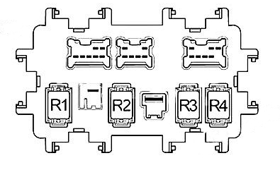
Relays
The several relay elements are located on the back of the unit: R1 – Ignition, R2 – Rear Window Defogger, R3 – Accessory, R4 – Front Blower.
Right box
It is present mainly in cars with a start-stop system.
Photo

Diagram

Designation
| 54 | 10A Steering wheel angle sensor |
| 55 | 10A Diode |
| 56 | 10A Audio system, Around View Monitor, distance sensor, front camera |
| 57 | 10A ECM, gearbox control unit, transmission range sensor, under-hood fuse box, neutral position sensor, primary speed sensor, secondary speed sensor, RPM sensor, reverse speed switch |
| 58 | Not used |
| 59 | 10A Air conditioner |
| 60 | 10A ABS, ABS control unit, Vehicle Dynamic Stability Control (VDC) |
| 61 | Not used |
| 62 | Not used |
| 63 | 20A Audio system, navigation control unit, Around View Monitor |
| 64 | Not used |
- R1 – Auxiliary relay
- R2 – Ignition
Engine compartment
There are 4 fuse boxes in the engine compartment. 2 boxes are located next to the battery, high power fuses on the battery terminal and behind the bumper on the side under the headlight is another additional one.

Access
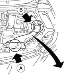

Fuse box A

Execution for example

Diagram

Designation
| 51 | 10A Active Grille Shutter, Engine Control Module |
| 52 | 15A Engine Control Module, EVAP Canister Purge Volume Control Solenoid Valve, Engine Coolant Bypass Valve Control Solenoid Valve, Fuel Heater and Water in Fuel Level Sensor, High Pressure Fuel Pump, Condenser, Ignition Coils, Exhaust Valve Timing Control Solenoid Valve, Intake Valve Timing Control Solenoid Valve, Fuel Injector Relay, High Pressure Fuel Pump Relay, Mass Air Flow Sensor, Heated Oxygen Sensor, Turbocharger Waste Gate Control Solenoid Valve, Air Fuel Ratio Sensor, Fuel Flow Actuator, Turbocharger Boost Control Solenoid Valve, Intake Valve Timing Intermediate Solenoid Valve, Intake Valve Timing Control Solenoid Valve, Turbocharger Bypass Control Valve, Engine Oil Pressure Control Solenoid Valve |
| 53 | 15A MR: Throttle Control Motor Relay |
| 54 | 10A Engine Control Module, Engine Coolant Bypass Valve Control Solenoid Valve, Intake Valve Timing Control Solenoid Valve, Engine Oil Pressure Control Solenoid Valve, Exhaust Valve Timing Control Solenoid Valve, Turbocharger Bypass Valve Control Solenoid Valve, Intake Manifold Runner Control Valve |
| 55 | 15A Engine Control Module, Heated Oxygen Sensor, Thermostat Heater Control Solenoid Valve, Glow Control Unit, Turbocharger Boost Control Solenoid, Air Fuel Ratio Sensor, Fuel Flow Actuator, Intake Manifold Runner Control Valve |
| 56 | 15A Engine Control Module, Steering Lock Unit |
| 57 | 15A Air Conditioner Relay |
| 58 | 10A Engine Control Module, Engine Restart Relay |
| 59 | – |
| 60 | 30A Front Wiper Hi/Lo Relay |
| 61 | 20A Fuel Pump Relay |
| 62 | – |
| 63 | 10A Transmission Control Module (TCM), Primary Speed Sensor, Output Speed Sensor, Transmission Range Switch, Input Speed Sensor, Ipdm E/R, Secondary Speed Sensor |
| 64 | – |
| 65 | 5A Engine Control Module, Steering Lock Unit |
| 66 | 10A Airbags, ABS system |
| 67 | 10A Headlamp Aiming Motor, Compressor, Transmission Range Switch, Front Window Defogger RH Relay, Front Window Defogger LH Relay, Reverse / Neutral Position Switch, Back-Up Lamp Switch, Neutral Position Switch |
Fuse box B
Diagram form the covery
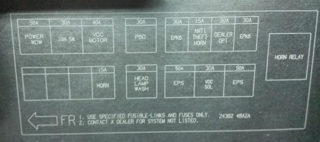
Diagram

Allocation
| 34 | 15A Horn (honk) (HORN) |
| 35 | 30A Diesel models: PTC Relay 2 Other models: Empty |
| 36 | 30A Diese models: PTC Relay 3 Other models: Empty |
| 37 | 30A Diese models: PTC Relay 1 Other models: Empty |
| 38 | 30A Electric parking brake control unit (EPKB) |
| 39 | 30A Optional connector (DEALER OPT) |
| 40 | 15A Anti Theft horn or Empty (not used) |
| 41 | 30A Electric parking brake control unit (EPKB) |
| F | 50A EPS – Electric power steering, Torque sensor, EPS motor (EPS) |
| G | 30A ABS – Anti-lock braking system, Vehicle dynamics control solenoid / ESP – Electronic Stability Program (VDC SOL) |
| H | 50A EPS – Electric power steering, Torque sensor, EPS motor (EPS) |
| I | 30A Headlight Washer Relay (HEAD LAMP WASH) |
| J | 30A Empty (not used) or (PBD) |
| K | 40A ABS – Anti-lock braking system, Vehicle dynamics control / ESP – Electronic Stability Program (VDC MOTOR) |
| L | 30A Ignition relay, Starter relay, (Fuses: 1, 2, 3, 4, 10, 11, 12) (IGN SW) |
| M | 50A Power Windows (electric windows), Power windows main switch, Sunshade motor assembly (curtain), Power seats switch (POWER WDW) |
| RELAY | |
| R1 | Horn (honk) relay (HORN RELAY) |
Relay box

Photo example and diagram on the back of the cover


| HEATED SCREEN | Heating glass |
| H/LAMP WASHER RELAY | Headlight washer relay |
| ANTI THEFT HORN RELAY | Anti-theft alarm relay |
| HEATED FRONT SCREEN RELAY | Heated windshield relay |
Battery-powered unit
It is located on the positive terminal of the battery, so this unit can be called simply – the terminal is positive and consists of fuses made in the form of a high-power fuse-link.

Diagram
Appointment
| A | 450A Alternator, starter (QR, MR), restart relay (start-stop), No. F fuse (ESP) |
| B | 100A Alternator, starter, restart relay (start-stop), fuse No. F (ESP) |
| 450A Alternator, starter, restart relay (start-stop), fuse # F (ESP) | |
| C | 100A Ignition, passenger compartment fuse box |
| D | 80A Fuse box in the engine compartment No. 3 |
| 100A Fuse box, fuse box (E137 – thermo plunger (R9M engine)) | |
| IS | 100A Passenger compartment fuse box |
| 50A Fuse box in the engine compartment No. 2 (F116) | |
| U | 100A Fuse box in the engine compartment No. 2 (F116), No. 3, ignition |
| V | 100А ESP |
We have posted a video on our YouTube channel. Watch and subscribe.
If you still have questions or know how to make the article better, write in the comments.
I need to find the headlight fuses and relays it’s not showing up in this video
hello, i am looking for the right hedlight fuse. i got a set of new light bulbs but it still not working. The left headlight is working and i swiched the bulbs to see if it was bad and it still not working. can any please help me.