The Nissan Murano Z50 is a full-size crossover that was produced in 2002, 2003, 2004, 2005, 2006, and 2007. During this period, the car underwent a restyling. In our article, you will find a description of the fuses and relays of the Nissan Murano Z50. For clarity, we will show photos and diagrams of the units, as well as the location of all electronic control units.

The car was sold in many countries around the world with different configurations. Therefore, the design of the blocks and the purpose of the elements in them may differ from those shown.
Contents
Blocks in the passenger compartment
Location
General layout of the blocks

Description
- Fuse box
- All-wheel drive control unit
- Body control module (BCM)
- Gear selector lock
- Immobilizer (NATS IMMU)
- Display control unit
- Air conditioning control unit
- Tire pressure monitoring system control unit
- Transmission control module (TCM)
- Engine control unit (ECM)
- Keyless entry control unit
- Airbag control unit
- Transfer case control unit
- Navigation control unit
- Driver Control Unit
- Time Control Unit
- Automatic Drive Positioner
Fuse box
In the vehicle interior, the fuse and relay block is located at the bottom of the instrument panel on the left-hand side.

Diagram from covery

Diagram
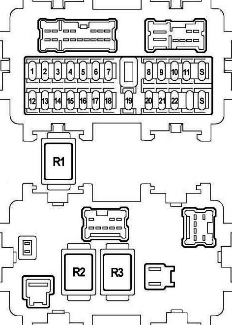
Assignment
| 1 | 10A Engine control unit |
| 2 | 10A Starter signal |
| 3 | 10A Heated seats |
| 4 | 10A Audio system |
| 5 | 15A Socket |
| 6 | 10A Heated mirrors, power mirrors, keyless entry, air conditioning, headlight range control, rear fog light, front fog lights, instrument cluster lights, antenna, headlight washer, audio system, combination switch, taillights, AV module |
| 7 | 15A Cigarette lighter |
| 8 | 10A Heated seats, air conditioning |
| 9 | 10A Seat memory |
| 10 | 15A Air Conditioner |
| 11 | 15A Air Conditioner |
| 12 | 10A Cruise Control, Diagnostic Connector, Speed Sensor, Transmission Selector, Transmission Indicators, Dynamic Stability Control (VDC), Keyless Entry, Nissan Anti-Theft System (NATS), Adaptive Lighting System (AFS), Rear Curtain, Buzzer , instrument panel illumination, instrument cluster, audio system, heated rear window, heated seats, headlight range control, taillights, air conditioning |
| 13 | 10A SRS |
| 14 | 10A Instrument Cluster: Instrument Panel Lights, Buzzer, Transmission Indicators, Transmission Selector (PNP), Cruise Control, Diagnostic Connector, Manual Shift Mode (CVT), ABS, Vehicle Dynamic Stability Control (VDC), SRS, Keyless Entry , rear curtain, charging system, headlights, front fog lights, rear fog light, turn signals and hazard warning lights, rear lights, reversing lamps, AV module |
| 15 | 15A Seat ventilation, headlight washer, glass washer |
| 16 | Not used |
| 17 | 15A Central locking, cruise control, diagnostic socket, transmission control unit, transmission oil temperature sensor, engine control unit, transmission selector, manual shift mode (CVT), vehicle dynamic stability control (VDC), keyless entry, anti-theft Nissan system (NATS), trunk lock, power windows, sunroof, heated rear window, power seats, seat memory, headlight range control, headlights, front fog lights, rear fog light, direction indicators and hazard warning lights, combination switch, rear switch, panel illumination instruments, instrument cluster, interior lighting, buzzer, gearbox indicators, AV module |
| 18 | 15A Gear selector lever, central locking, keyless entry, Nissan Anti-Theft System (NATS), seat memory, interior lighting, buzzer |
| 19 | 10A Engine mounts, diagnostic connector, manual shift mode (CVT), vehicle dynamic stability control (VDC), keyless entry, Nissan anti-theft system (NATS), air conditioning, taillights, instrument panel lights, instrument cluster, buzzer, AV module , transmission indicators |
| 20 | 10A Brake lights, brake light switch, cruise control, vehicle dynamic stability control (VDC), ABS, gear selector |
| 21 | 10A Interior lighting, visor mirror illumination |
| 22 | 10A Fuel filler cap |
| S | Spare fuse |
Fuse number 7, 15A, is responsible for the cigarette lighter
The heater fan relay and the auxiliary ignition circuit relay can be located on the side.
- R1 – Seat heating relay
- R2 – Heater relay
- R3 – Relay additional equipment
Blocks in the engine compartment
Location
Layout

Appointment
- Power fuse box
- Fuse box No. 2
- Fuse box No. 1 (IPDM E/R)
- ABS control unit
- Windscreen wiper motor
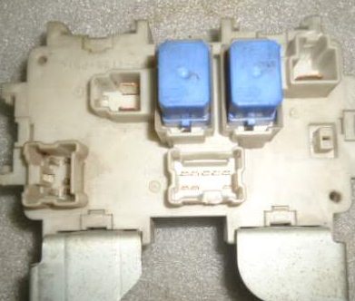
Fuse box 2
Location

The photo

Diagram from covery

Diagram

Designation
| 1 | Headlight washer relay |
| 2 | Horn relay |
| F1 | – |
| F2 | (10A) Horn |
| F3 | (10A) Generator |
| F4 | (30A) Trailer socket |
| F5 | (50A) |
| F6 | – |
| F7 | (30A) ABS / ESP system |
| F8 | (40A) Headlamp washers |
| F9 | (50A) ABS / ESP system |
| F10 | (40A) Cooling fan motor |
| F11 | (40A) Cooling fan motor |
| F12 | (40A) Ignition switch circuits |
| F13 | (10A) Tailgate opener |
| F14 | (15A) Heated seats |
| F15 | (10A) 4WD control system |
| F16 | (15 A) |
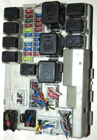
Fuse box 1
Located on the right side rail and turned on its side.
The photo
Diagram
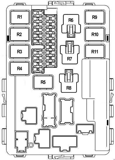
Allocation
| Circuit breakers | |
| 71 | 15A side lights |
| 72 | 10A High beam, right side |
| 73 | 20A Wiper relay |
| 74 | 10A High beam left side |
| 75 | 20A Heated rear window |
| 76 | 10A Right side low beam |
| 77 | 15A Main relay, ECM, Nissan anti-theft system (NATS) |
| 78 | 15A Fuse and relay box |
| 79 | 10A A / C relay |
| 80 | Not used |
| 81 | 15A Fuel pump relay |
| 82 | 10A Anti-lock braking system (ABS), Vehicle Dynamic Stability Control (VDC) |
| 83 | 10A ECM, speed sensor, gearbox control unit, gearbox oil temperature sensor, speed sensor (CVT), starter |
| 84 | 10A Windscreen wiper and washer |
| 85 | 15A Heated oxygen sensor |
| 86 | 15A Low beam left side |
| 87 | 15A Throttle body |
| 88 | 15A Front fog lamps |
| 89 | 10A Engine control unit |
| Relay | |
| R1 | Main relay |
| R2 | Headlamp high beam relay |
| R3 | Headlamp low beam relay |
| R4 | Starter relay |
| R5 | Ignition relay |
| R6 | Cooling fan relay 3 |
| R7 | Cooling fan relay 1 |
| R8 | Cooling fan relay 2 |
| R9 | Throttle valve relay |
| R10 | Fuel pump relay |
| R11 | Fog lamp relay |
Power fuses box
The positive side of the battery may contain high power fuses.
Diagram

Purpose
- A – 120A Generator, fuses: “B”, ‘C’
- B – 100A Fuses: “31”, “32”, “33”, “34”, “35”, “36”, “37”, “38”, “F”, “G”, “H”, “I”, “J”, “K”, ‘L’, “M”
- C – 80A Option 1: High beam relay (fuses: “85”, “86”), low beam relay (fuses: “83”, “84”), fuses: “72”, “74”, “75”, “76”, ‘77’, “79”
Option 2: High beam headlight relay (fuses: “72”, “74”), low beam headlight relay (fuses: “76”, “86”), fuses: “71”, “73”, ‘75’, “87” - D – 60A Auxiliary relay (fuses: “5”, “6”, “7”), heater motor relay (fuses: “10”, “11”), fuses: “17”, “18”, “19”, ‘20’, “21”
- E – 80A Option 1: Ignition relay (fuses: “71”, “80”, “81”, “87”, “88”), fuses: “73”, ‘78’, “82”
Option 2: Ignition relay (air conditioning relay, front windshield wiper relay, front windshield wiper relay – high speed, fuses: “81”, “82”, “83”, “84”), fuses: “77”, ‘78’, “79”, “80”
Check out our YouTube video for more on this topic. Don’t forget to subscribe!
And if you have something to supplement the material, we will be glad to receive your comments.
My 2 audio amp and woofer amp compartment fuse are missing on my murano 2012, no sound on radio, please any help
Hello, Thank you for this. do any happen to know which one of these fuses would control the moonroof on a 2015 Murano Platinum?