The Nissan Pulsar C13 was produced in 2014, 2015, 2016, 2017, 2018, 2019, 2020. In this publication, we will describe the fuses and relays in the Nissan Pulsar C13, including fuse box diagrams, their locations, and photo examples.

The purpose of the fuses and relays may differ from that shown and depends on the year of manufacture and the level of electrical equipment of your vehicle.
Passenger compartment
Located at the end of the dashboard, behind the side cover.
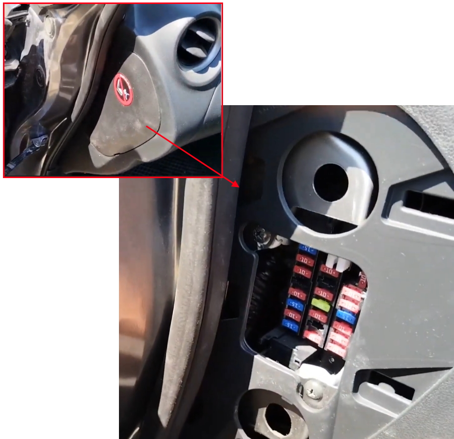
Check the assignment of the elements against your diagram on the back of the protective cover.
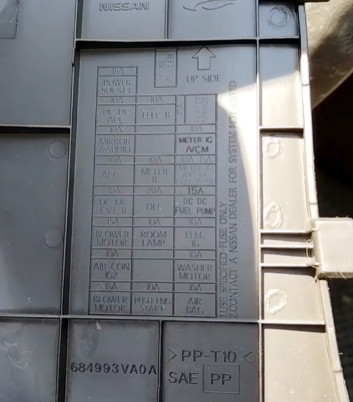
Photo – Diagram

Designation
| F1 | 20A Socket for connecting additional equipment, cigarette lighter, audio system, electric drive of outside rear-view mirrors |
| F2 | 10A Audio system |
| F3 | 10A Mounting block in the engine compartment |
| F4 | 15A Blower fan relay |
| F5 | 10A Air conditioner |
| F6 | 15A Blower fan relay |
| F7 | 10A Optional equipment |
| F8 | 10A Instrument cluster |
| F9 | 20A Trailer electrical equipment |
| F10 | 10A Interior lighting plafond |
| F11 | 15A Heated seats |
| F12 | 10A Heated exterior mirrors |
| F13 | 10A Instrument cluster |
| F14 | 10A Optional equipment |
| F15 | 10A Optional equipment |
| F16 | 10A Washers |
| F17 | 10A Passive Restraint System (SRS) |
| R1 | Relay additional equipment of salon |
| R2 | Blower fan relay |
The fuse number 1, 20A, is responsible for the cigarette lighter.
Here is a video example of accessing the unit and replacing the fuse.
Engine compartment
Location

Fuse box 2

Photo of fuse box

Description of the 1st mounting box

Diagram

Circuits protected
| 81 | 10A Engine control unit |
| 82 | 15A Engine control unit, |
| 83 | 15A Throttle valve, engine control unit, canister valve (EVAP), MAF sensor, ignition coils, main relay, exhaust valve, inlet valve, high pressure fuel pump, injectors, engine compartment fuse box, air-fuel ratio sensor, heater fuel, water-in-fuel sensor, coolant bypass valve |
| 84 | 10A Engine control unit, intake manifold valve, timing valve exhaust, timing valve inlet, timing valve |
| 85 | 15A Air fuel ratio sensor, heated oxygen sensor, turbocharger valve, engine control unit, glow plug control unit |
| 86 | 15A Injectors, ignition coils, fuse box |
| 87 | 15A A / C compressor relay |
| 88 | Not used |
| 89 | Not used |
| 90 | 30A Front wiper relay, front wiper motor |
| 91 | 20A Fuel pump relay |
| 92 | Not used |
| 93 | 10A ECM, gearbox control unit, transmission range sensor, under-hood fuse box, neutral position sensor, primary speed sensor, secondary speed sensor, rev sensor, reverse / neutral sensor |
| 94 | Not used |
| 95 | 5A Steering wheel lock block |
| 96 | 10A Relay restart (start-stop) |
| 97 | 10A Front right combination lamp, front left combination lamp, compressor, transmission range sensor, under-hood fuse box, neutral position sensor, reverse speed switch, reverse / neutral sensor |
Fuse box 3
Photo for example

Diagram from covery

Designation
| FL60A EPS | Electric Power Steering (main power supply) |
| FL50A RAD FAN | Radiator cooling fan (main power feed) |
| FL40A VDC SOL | Vehicle Dynamic Control solenoid valves |
| FL40A IGN SW | Ignition switch circuit |
| FL40A VDC MTR | VDC motor circuit |
| FL40A P/WDW | Power windows |
| FL30A HEAD LAMP | Headlight power feed |
| FL30A WASH | Windshield washer system |
| FL30A DC/DC | DC-DC converter (charging and voltage step-down circuit) |
| FL30A PTG 1 | Power terminal group 1 (e.g., accessory systems) |
| FL30A PTG 2 | Power terminal group 2 |
| FL30A PTG 3 | Power terminal group 3 |
| FL20A FUEL HEATER | Diesel fuel heater (if equipped) |
| FL20A ANTI THEFT | Anti-theft system or immobilizer module |
| FL15A DOOR LOCK 1 | Power door lock control (front) |
| FL15A DOOR LOCK 2 | Power door lock control (rear) |
| FL10A HORN | Horn circuit |
| FL10A VDC MIR | Vehicle Dynamic Control mirror or sensor supply |
| FL10A ANT1 | Antenna amplifier or telematics module |
| FL10A ANT2 | Secondary antenna circuit |
Power fuse box 4
It is located on the positive terminal of the battery and is a group of fusible links that protect the fuse boxes in the passenger compartment and under the hood. On the diagrams it is marked with number 4. In case of complete absence of voltage, we recommend starting the test with them.

Check out our YouTube video for more on this topic. Don’t forget to subscribe!
If you have any questions, write in the comments.
Good morning, I would like to ask something about the Fuses that are on the battery, of a Nissan pulsar 1.5d , 2015 model. There is a fuse box with 5 fuses this has to be changed all together if 1of them is burned ? And what is the cost of that?
Thank you.