The 7th generation Mitsubishi Fuso Canter was produced in 2002, 2003, 2004, 2005, 2006, 2007, 2008, 2009, 2010 and 2011 with various versions of both the body and the cab. During this period, the model also underwent restyling. In this regard, there is no one general description of fuses and relays. In this material, we will consider the most common arrangement of electronic control units and the purpose of fuses and relays in them for Mitsubishi Fuso Canter 7.

Check the purpose of the elements with your diagrams on the protective cover.
Passenger compartment fuse box
The dashboard usually contains 2 relay blocks and one fuse.
General layout of control units in the passenger compartment
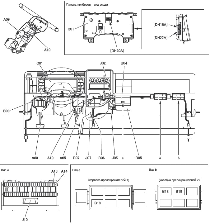
Decoding
- A 05 idle speed control potentiometer
- A 08 clutch switch
- A 09 starter switch
- A 10 switch combination
- A 13 connection for diagnostics
- A 14 memory clearing connection
- A 19 accelerator pedal position sensor
- C 01 instrument panel
- J 02 connection connector
- J 10 device connector Multi-Use tester
- B 04 fuse box
- B 05 engine ECU
- B 06 diode
- B 07 CAN resistor
- B 09 fuel injection resistor
- B 13 safety relay
- B 18 ABS emission stop relay
- B 19 glow plug relay
Fuse box
Remove the protective cover for access.
the photo
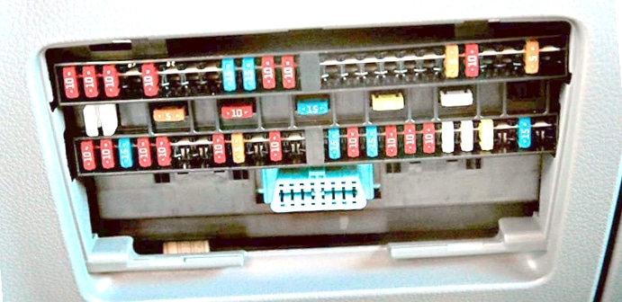
Diagram from the block cover
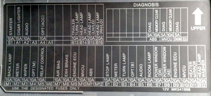
Diagram

Assignment
| A1 | 10A Cigarette lighter |
| A2 | 10A Audio |
| A4 | 10A Additional power unit (ACC ignition switch) |
| V1 | 15A Brake signal lamp |
| V2 | 10A Instrument cluster (EURO-3) Flow meter unit (EURO-4) |
| B3 | 15A Turn signal lamps |
| B4 | 10A Additional power supply (the circuit is directly connected to the battery) |
| B5 | 10A Audio |
| B6 | 10A Interior light |
| B7 | 25A Electric glass lift (driver) |
| AT 8 | 25A Electric glass lift (passenger) |
| B9 | 20A engine ECU |
| B11 | 15A Heated mirrors |
| В13 | 15A Diagnostic connector Tester |
| B14 | 15A Headlights (high beam) |
| B15 | 10A Left headlight (low beam) |
| V16 | 10A Right headlight (low beam) |
| B25 | 15A Rear lights |
| V26 | 15A Rear fog lamps |
| B27 | 10A Sound signal |
| B28 | 5A Air conditioner |
| B29 | 15A Air conditioner condenser fan |
| ВЗ0 | 15A Air conditioner fan, heater fan |
| B33 | 15A Fuel heater |
| В36 | 20A Exhaust gas recirculation motor Engine control unit |
| M1 | 10A Reversing lights |
| M2 | 10A Instrument cluster (EURO-3) Flow meter unit (EURO-4) |
| M3 | 15A Screen wiper and washer |
| M4 | 10A Auxiliary Power Supply (Ignition Switch Circuit ON) |
| M5 | 10A Exhaust gas recirculation control relay |
| M8 | 10A Exhaust brake |
| M9 | 5A engine ECU |
| M11 | 10A ABS |
| S1 | 10A Starter |
| * | Spare fuse |
| 1 | 5A Elimination of malfunctions of the ABS (diagnostics) |
| 2 | 10A Troubleshooting ABS (clear memory) |
| 3 | 5A Elimination of malfunctions of the engine ECU (diagnostics) |
| 4 | 10A Eliminating engine ECU malfunctions (clear memory) |
The fuse number A1 for 10A is responsible for the cigarette lighter.
Box near the battery
Another block is attached to the outside of the car next to the battery.

The photo

Diagram with designation

Appointment
| B25 | 15A Rear lights |
| V26 | 15A Rear fog lamps |
| B27 | 10A Sound signal |
| B28 | 5A Air conditioner |
| B29 | 15A Air conditioner condenser fan |
| ВЗ0 | 15A Air conditioner fan, heater fan |
| B33 | 15A Fuel heater |
| В36 | 20A Exhaust gas recirculation motor Engine control unit |
| FH1 | 60A Fuse box (S1, A1-A4, M1-M12) |
| FH2 | 60A Fuse Box (B1-B11) |
| FH3 | 30A Fuse Box (B13-B16) |
| FH7 | 30A ABS engine |
| FH8 | 30A ABS Solenoid Switch |
| BATT1 | 120A Alternator |
If the engine has an engine heater and an indicator light and does not light up in cold weather, check for a blown heat relay fuse (1). If it is blown, disconnect the (-) wire from the battery and replace the fuse with a new 127A.

If you have any questions, write in the comments.
Quiero todo el diagrama electricidad de 24v completo
Is there a separate fuse for the rear number plate light?
Usually, no
Hi, I am after the wiper fuse or the relay for Mitsubishi Fuso Canter 515, 2021.
I do not know where its location in the fuse box. Thanks
Very helpful information indeed
My fuso with 4m50 engine has problems at the time pass over a bump it starte smoking and miss all so loose power withen 5 minute it’s ok
And the same to has morning starting
Issues with non starting
Is there a fuel pump fuse/relay?
not in the passenger cab or box near the battery???
I’ve always thought the fuel pump is run from the crank or engine start but being told there is a fuel pump relay somewhere??
Any help gratefully received