The 4th generation Mitsubishi Delica minivan was produced in 1994, 1995, 1996, 1997, 1998, 1999, 2000, 2001, 2002, 2003, 2004, 2005, 2006. During this time, the Delica underwent restyling. Delivered all over the world. In some countries it is known as Mitsubishi L400, Mitsubishi Space Gear. The cargo model is called Delica Cargo. On the territory of the CIS, cars are sold that were supplied both to Europe (left hand drive) and Japan (right hand drive). In this publication you will find a description of the 4th generation Mitsubishi Delica fuses and relays with box diagrams and locations. Let’s highlight the fuse responsible for the cigarette lighter.

Depending on the region of delivery and the level of equipment, there may be a difference in the design of the boxes and the purpose of their elements.
Contents
Passenger compartment fuses and relay boxes
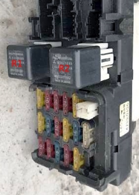
Fuse and relay box
Located at the bottom of the instrument panel on the left side.
For example
Diagram
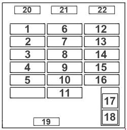
Assignment
| 1 | 10A Sound signal |
| 2 | 10A Heater |
| 3 | 15A Cigarette lighter |
| 4 | 10A Automatic transmission control system |
| 5 | 20A Electric blinds (right-hand drive models) |
| 6 | 20A Heated rear window |
| 7 | 15A Heated seats (except for models from 2000) |
| 8 | 10A Instrumentation |
| 9 | 20A Windshield washer and wiper |
| 10 | 15A ETACS system and central locking (RHD models from 1998) |
| 11 | 25A Electric fan, front heater |
| 12 | 20A Rear heater fan |
| 13 | 10A ECS and ABS systems |
| 14 | 10A Rear code lights |
| 15 | 10A Direction indicators and hazard warning lights |
| 16 | 20A Socket for connecting an additional |
| 17 | Heated rear window |
| 18 | Heater |
| 19 | Spare fuse |
| 20 | Spare fuse |
| 21 | Spare fuse |
| 22 | Spare fuse |
The fuse number 3, 15A, is responsible for the cigarette lighter.
- R1 – Rear window defogger relay
- R2 – Front heater fan motor relay
Relay box
Mounts close to the fuse box.
Diagram

Designation
- C-60X – Central locking relay
- C-61X – Relay – direction indicator and alarm interrupter
- C-62X – Rear heater fan motor relay
- C-62X – Rear Heater Fan Motor Hi Mode Relay
- C-63X – Relay for connection socket for additional heater
- C-64X – Tailgate relay
- C-65X – Relay for electric drive glass lifters
Engine compartment fuse box
Located on the right side of the engine compartment.

The photo

diagram

Assignment
| 1 | 10A High beam headlights |
| 2 | 10 / 15A Air Conditioning Compressor |
| 3 | 10A Dimensions (left) (LHD models) |
| 3 | 15A Fog lights (right-hand drive models) |
| 4 | 10A Dimensions (right for left-hand drive models) |
| 5 | 10A Interior lighting |
| 6 | 15A Radio tape recorder, Socket for connecting additional equipment |
| 7 | 10A Stop – signals |
| 8 | 20 / 30A Electro fan of the front condenser |
| 9 | 10 / 15A Electro side condenser fan |
| 10 | 15A Fuel wire heater (LHD models) |
| 10 | 15A Heated wiper blades (right-hand drive models) |
| 11 | 10A Alarm |
| 12 | 20A Intercooler of charge air |
| 13 | 30A Power windows, Central locking |
| 14 | 50A ABS system |
| 15 | 40A Outdoor lighting |
| 16 | 30A Electric sunroof and roof blinds |
| 17 | 100A Generator |
| 18 | 80A Accumulator, battery |
Relay
- ALTERNATOR – Generator
- AIR CON COMPRESSOR – Air conditioning compressor
- CONDENSOR FAN FRONT – Front fan condenser
- CONDENSOR RAER FRONT – Rear fan condenser
- HEAD LIGHT – Headlight relay
- HORN – Signal relay
- INTERCOOLER FAN – Intercooler fan relay
- FRONT FOG LIGHT – Front fog lamp relay
- WIPER DE-ICER – Relay for cleaner and heater
On the positive terminal of the storage battery, fuses made in the form of a high-power fuse can also be installed.
Musudapisi fuso Rosa bus fuse location and wiring diagram need sir